This thread has been locked.

If you have a related question, please click the "Ask a related question" button in the top right corner. The newly created question will be automatically linked to this question.

About LDC0851 documents & tools

Other Parts Discussed in Thread: LDC0851, LDC0851EVM

Hello ...

I am currently designing a ldc0851.
I have some questions about documents and tool

documents and tools:
ldc0851 Differential Inductive Switch (Rev. A)
slyc137 Inductive Sensing Design Calculator Tool
WEBENCH Coil Designer

------------------------------------
Q1) 9.1.1.1 Sensor Frequency (Page 19)
The formula is correct?
Fsensor = root(2) / [2 * pi * root(Lsensor * Ctotal)]

This is not?
Fsensor = 1 / [2 * pi * root(Lsensor * Ctotal)]

------------------------------------
Q2) 9.1.1.2 Sensor Design Procedure (Page 20)
The formula is correct?
Csensor = {1 / [(pi * Fsensor)^2 * (2 * Lsensor)]} - Cboard - Cin_com

This is not?
Csensor = {1 / [(pi * Fsensor)^2 * (4 * Lsensor)]} - Cboard - Cin_com

or
Csensor = {1 / [(2 * pi * Fsensor)^2 * Lsensor]} - Cboard - Cin_com

------------------------------------
Q3) 9.2.3.2 Detailed Design Procedure (Page 25)
If the frequency is 10 Mhz, is that one sample(Fsample) time how long?

------------------------------------
Q4) slyc137 Inductive Sensing Design Calculator Tool (sheet 3 - LDC0851_calc)
at CELL C12

The formula is correct?
=1000/(SQRT(2)*PI()*SQRT(C11*C8))

This is not?
=1000/(2*PI()*SQRT(C11*C8))

------------------------------------
Q5) The LDC0851EVM's PCB infomation?
How lmany space between 1st layer and 2nd layer(x12)
How many space between 2nd layer and 3rd layer(x23)

------------------------------------
Q6) WEBENCH Coil Designer (LDC0851)
At 4: Select Coil Geometry And Other Parameters

In calculating the inductance, How many use layers?

------------------------------------
Q7) WEBENCH Coil Designer (LDC0851) and WEBENCH Coil Designer (Custom)
Two inductance values are similar,
Why are the two calculations differ in sensor frequency?


WEBENCH Coil Designer (LDC0851)
Conditions are as follows:

LC sensor capacitance(C) : 50 pF
Outer diameter of inductor(Dout) : 20 mm
Turns per layer(N) : 10 Turns
Trace width(W) : 0.2 mm
Spacing between traces(S) : 0.2 mm
Copper thickness(t) : 1 oz-Cu
Temperature(T) : 25 C
Space between 1st layer and 2nd layer(x12) : 0.2 mm
Space between 2nd layer and 3rd layer(x23) : 0.6 mm
Space between 3rd layer and 4th layer(x34) : 0.2 mm

WEBENCH Coil Designer (Custom)
Conditions are as follows:

LC sensor capacitance(C) : 50 pF
Outer diameter of inductor(Dout) : 20 mm
Layers(M) : 2 Layer
Turns per layer(N) : 10 Turns
Trace width(W) : 0.2 mm
Spacing between traces(S) : 0.2 mm
Copper thickness(t) : 1 oz-Cu
Temperature(T) : 25 C
Voltage (Oscillation Amplitude)(V) 1.8V
Space between 1st layer and 2nd layer(x12) : 0.2

------------------------------------
Q8) If the two results is correct, question Q7

In the WEBENCH Coil Designer (LDC0851),

Except LC sensor capacitance (C),

How much value addition to the capacitance (C) were using the Cboard, Clcom ?

Thank you
:)

  • Hello,

    Let me address your questions below:

    Yang Kyoung Min said:

    Q1) 9.1.1.1 Sensor Frequency (Page 19)

    The formula is correct?
    Fsensor = root(2) / [2 * pi * root(Lsensor * Ctotal)]

    This is not?
    Fsensor = 1 / [2 * pi * root(Lsensor * Ctotal)]

    The LDC0851 has a set of different equations than our traditional LDC devices . The formula in the datasheet is correct with the square root 2 in the numerator:

    Yang Kyoung Min said:

    Q2) 9.1.1.2 Sensor Design Procedure (Page 20)
    The formula is correct?
    Csensor = {1 / [(pi * Fsensor)^2 * (2 * Lsensor)]} - Cboard - Cin_com

    This is not?
    Csensor = {1 / [(pi * Fsensor)^2 * (4 * Lsensor)]} - Cboard - Cin_com

    or
    Csensor = {1 / [(2 * pi * Fsensor)^2 * Lsensor]} - Cboard - Cin_com

    If you solve the sensor frequency equation for CTOTAL you get the following equation:

    Then CTOTAL is defined as the sum of the capacitance on the LCOM pin:

    CSENSOR is the discrete capacitor placed on the board, so these equations can be combined into one:

    Yang Kyoung Min said:

    Q3) 9.2.3.2 Detailed Design Procedure (Page 25)
    If the frequency is 10 Mhz, is that one sample(Fsample) time how long?

    This design example is referring to powering down the device and powering it back up to get an effective sample rate (fsample).

    The active conversion time of the LDC0851 is determined by the sensor frequency as shown in equation 2 in the datasheet:

    For a sensor frequency of 10MHz, the conversion time (which is the latency to update the output to a new state) is 432.9 µs. This would represent an active update rate of 2.3ksps. By duty cycling the part you could achieve a much slower sample rate (fsample) which results in power savings. The example uses a power cycled sample rate (fsample) of 1 sps to achieve an average current consumption of 1.867µA.

    Yang Kyoung Min said:

    Q4) slyc137 Inductive Sensing Design Calculator Tool (sheet 3 - LDC0851_calc)
    at CELL C12

    The formula is correct?
    =1000/(SQRT(2)*PI()*SQRT(C11*C8))

    This is not?
    =1000/(2*PI()*SQRT(C11*C8))

    Correct, this tab properly converts the frequency with an equivalent version of the formula: 

    The tool includes a 1000 in the numerator for unit conversion to get to MHz.

    Yang Kyoung Min said:

    Q5) The LDC0851EVM's PCB infomation?
    How lmany space between 1st layer and 2nd layer(x12)
    How many space between 2nd layer and 3rd layer(x23)

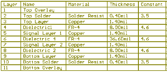
    The EVM is a 4 layer PCB where the spacing between the 1st and 2nd (x12) is 8mil, x23 = 36.6mil, x34=8mil. The layer stackup is shown below:

    Yang Kyoung Min said:

    Q6) WEBENCH Coil Designer (LDC0851)
    At 4: Select Coil Geometry And Other Parameters

    In calculating the inductance, How many use layers?

    The webbench tool for the LDC0851 calculator calculates inductance for 2 layers, but the PCB has 2 stacked coils so there is 4 total layers. You can export the design to a CAD tool and see the layout that it generates:

    Yang Kyoung Min said:

    Q7) WEBENCH Coil Designer (LDC0851) and WEBENCH Coil Designer (Custom)
    Two inductance values are similar,
    Why are the two calculations differ in sensor frequency?


    WEBENCH Coil Designer (LDC0851)
    Conditions are as follows:

    LC sensor capacitance(C) : 50 pF
    Outer diameter of inductor(Dout) : 20 mm
    Turns per layer(N) : 10 Turns
    Trace width(W) : 0.2 mm
    Spacing between traces(S) : 0.2 mm
    Copper thickness(t) : 1 oz-Cu
    Temperature(T) : 25 C
    Space between 1st layer and 2nd layer(x12) : 0.2 mm
    Space between 2nd layer and 3rd layer(x23) : 0.6 mm
    Space between 3rd layer and 4th layer(x34) : 0.2 mm

    WEBENCH Coil Designer (Custom)
    Conditions are as follows:

    LC sensor capacitance(C) : 50 pF
    Outer diameter of inductor(Dout) : 20 mm
    Layers(M) : 2 Layer
    Turns per layer(N) : 10 Turns
    Trace width(W) : 0.2 mm
    Spacing between traces(S) : 0.2 mm
    Copper thickness(t) : 1 oz-Cu
    Temperature(T) : 25 C
    Voltage (Oscillation Amplitude)(V) 1.8V
    Space between 1st layer and 2nd layer(x12) : 0.2

    The difference in frequency comes from the fact that the LDC0851 uses an extra square root 2 factor. Therefore for the same inductance the LDC0851 will oscillate at a faster frequency by a factor of sqrt(2).

    Yang Kyoung Min said:

    Q8) If the two results is correct, question Q7

    In the WEBENCH Coil Designer (LDC0851),

    Except LC sensor capacitance (C),

    How much value addition to the capacitance (C) were using the Cboard, Clcom ?

    The tool calculates the frequency with CTOTAL. You should convert this to CSENSOR by assuming CIN_COM = 12pF and CBOARD from the final parasitic from your PCB design. Typically ~4-5pF is a good approximation.

    Regards,
    Luke 

  • All questions are solved clarity
    Thank you
    Best regards
    Yang