This thread has been locked.

If you have a related question, please click the "Ask a related question" button in the top right corner. The newly created question will be automatically linked to this question.

Problems measuring larger capacitances

Dear all,

I ordered 2 EVM of the FDC 2214. While trying them out I found, that they measure capacitance from 0 to approx. 200pF very well.

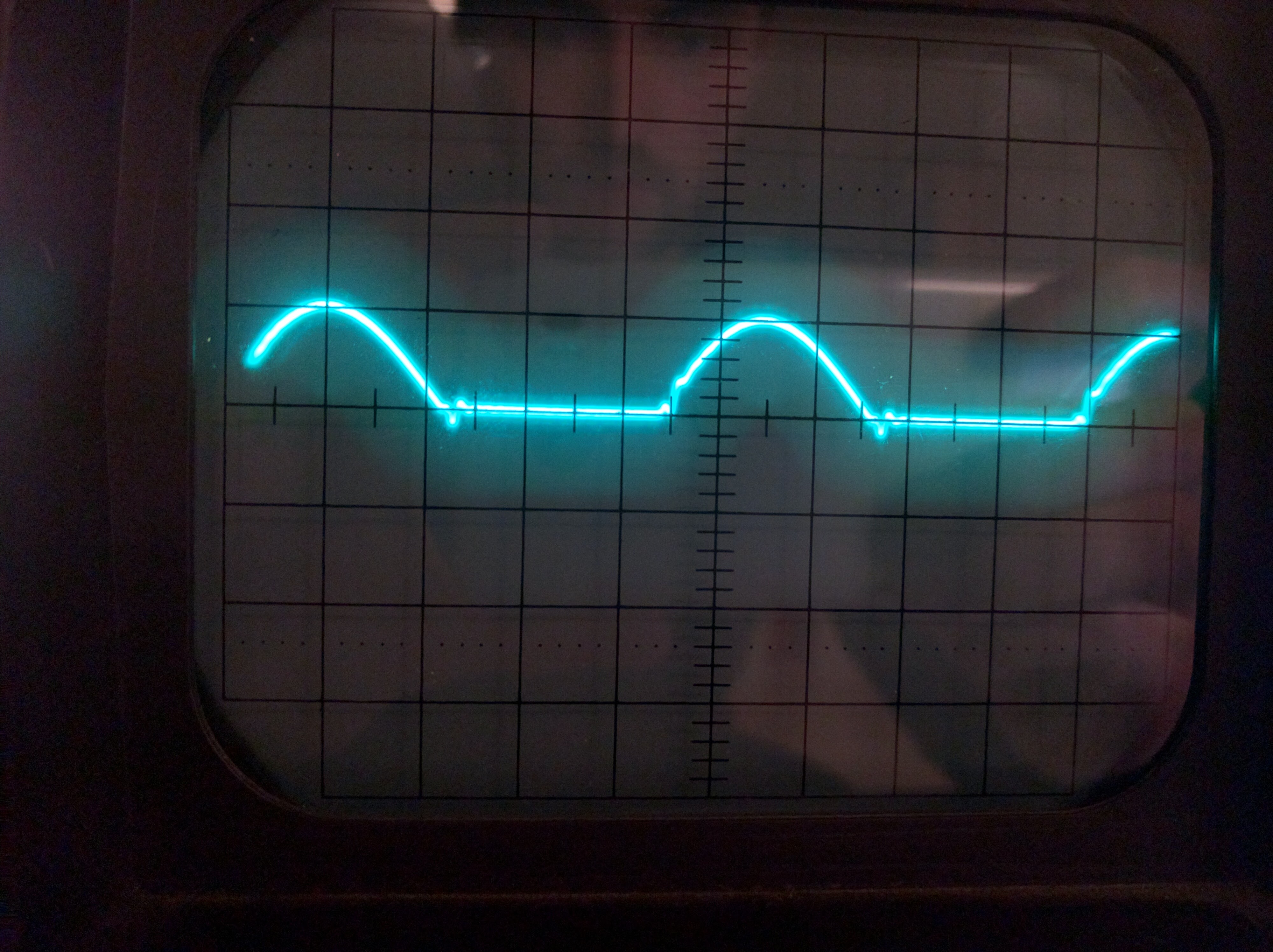
When I increase the capacitance into the range of nF it starts measuring wrong (either too high or too low or both within a second).

I used the EVM in differential mode. The registers were set as follows:

(registers adress, MSB, LSB)

{0x00,0x01,0x51},
{0x02,0x02,0x18},
{0x04,0x02,0x2F},
{0x06,0x02,0x16},
{0x08,0xFF,0xFF},
{0x09,0xFF,0xFF},
{0x0A,0xFF,0xFF},
{0x0B,0xFF,0xFF},
{0x0C,0x00,0x00},
{0x0D,0x00,0x00},
{0x0E,0x00,0x00},
{0x0F,0x00,0x00},
{0x10,0x04,0x00},
{0x11,0x04,0x00},
{0x12,0x04,0x00},
{0x13,0x04,0x00},
{0x14,0x10,0x01},
{0x15,0x10,0x01},
{0x16,0x10,0x01},
{0x17,0x10,0x01},
{0x18,0x00,0x48},
{0x19,0x00,0x01},
{0x1A,0x36,0x41},
{0x1B,0x02,0x09},
{0x1C,0x00,0x00},
{0x1E,0xF8,0x00},
{0x1F,0x8C,0x40},
{0x20,0x88,0x00},
{0x21,0x88,0x00},
{0x7E,0x54,0x49},
{0x7F,0x30,0x54},

I tried out to change many of the parameters (such as: deglitch, clock divider, interrupt, high power mode, input amperage...) without getting a better result.

Anyone any idea? I am basically just trying to measure the capacitance of capacitors, so it should be easy.

Thank you in advance

  • Hello Adrian,

    In my application the system should be very sensitive. It is about proximity sensing. Try using this register values.

    {Only modify this registers...(Restart your EVM and try it)}

    {R Address, MSB, LSB}

    {0x08, 0x9C, 0x40},

    {0x10, 0x00, 0x64},

    {0x1B, 0x02, 0x0D},

    {0x1E, 0xF8, 0x00}, // With this register modify bit by bit  [15:11] so that, the remaining bits are reserved. [0 1 0 1 1 R R R R R R R R R R R] Ensure with an oscilloscope the oscillation is: 1.2v<Vpk<1.8V.

    {0x1A, 0x1E, 0x01},

    Thanks. 

    Josue

  • Hi Adrian,

    Josue makes some good points. Please check your oscillation amplitude and make sure it's a clean half-sine wave. Let us know if it works!

    Thanks,
    Rachel
  • Hi,
    thanks for your help so far. I tried to increase the current in 0x1E bit by bit. I was still not able to measure capacitances larger, than 200pF. I measured a normal sin-wave in the LC circuit. (not a half-sin) I thought it would have to be a normal sin wave, as shown in the datasheet on page 16 figure 14. I measured the frequency on the oscilloscope and transformed it into a value for the capacitance. It works fine as long as it stays above the 0.8 V.
    Do you know why my FDC sends out a whole sin wave? That might be the problem with my application.

    Thank you,
    Adrian
  • Update: I solderd a pin into the connection holes of ch0. When i hold the capacitance directly onto the pins it measures its value. As soon as I use a little wire to connect the capacitance it doesnt work anymore. It still shows me a full sin-wave all the time. The amplitude falls down dramatically when I connect a capacitance. It probably gives me wrong values due to the very low amplitude.
    Anyone any idea?
    Thank you!
  • Hi Adrian,

    Could you post a picture of the signal on the oscilloscope? Were there any other changes you made to the EVM? It shouldn't output a full sine-wave.

    You can try to increase your IDRIVE until the sensor oscillation amplitude is within the recommended operating range of 1.2 V and 1.8 V. 

    Thanks,

    Rachel

  • Hi Rachel,
    there are a few new things I found out recently:

    1. The EVM measures the capacitance correctly, when I press the capacitor directly onto the contacts on the board. A nice half sin wave within the range of 0.8 and 1.2 V appears on the oscilloscope.

    2. As soon as I connect a wire (10cm) to the contacts the result increases a little (as it should, due to the wire's capacitance) But when I connect my 8.2 nF capacitor to the wiring the half sin wave changes just a little bit (compare the pictures)and the evm tells me its measuring roughly 900pF. When I connect a larger capacitance I can not make out anything similar to the half sin wave. I added the choke and the additional capacitors onto the board, hoping it would solve this problem. Unfortunately it didn't.

    8.2 nF without wiring:
    www.bilder-upload.eu/show.php

    8.2nF with wiring:
    www.bilder-upload.eu/show.php

    There must be some source of EMI or something else disturbing my signal?!

    Anyone any idea?

    Thanks,

    Adrian
  • Hi Adrian,

    Thanks for the new information. Could you attach the images to your message or show a screenshot? I can't view the links you sent. Also, could you clarify how you connected the capacitor to the board? Do you connect from INA to INB or INA to GND?

    Thanks,
    Rachel
  • Hi everyone,

    Sorry, I used the wrong links. These ones should work:

    With wiring
    www.bilder-upload.eu/show.php

    Without wiring (works)
    www.bilder-upload.eu/show.php

    With large capacitances attached to the wiring (other settings on the oscilloscope)
    www.bilder-upload.eu/show.php

    I tried both, the single ended and the differential connections.


    Thanks,

    Adrian

  • Hi Adrian,

    Sorry I wasn't clear earlier: the bilder-upload.eu is a blocked site. Can you directly attach the images to your messages or paste a screenshot?

    Thanks,

    Rachel

  • With a large capacitance connected (no correct measurement)

    8nF with wires (roughly 10cm)

    No wiring -> correct measurement

  • Hi Adrian,

    Thanks for the pictures. I have a couple of questions - what is the amplitude and frequency of the oscillation for the three waveforms? Are these particular waveforms for the single-ended or differential configuration? Also, what kind of capacitor are you using?

    Thanks,

    Rachel