This thread has been locked.

If you have a related question, please click the "Ask a related question" button in the top right corner. The newly created question will be automatically linked to this question.

PGA900 4-20 Mode Application

Other Parts Discussed in Thread: PGA900

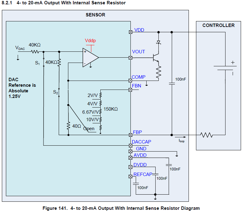
The image above is taken from SLDS209A pg118. 

1.  Which register controls S2?

2.  When S2 is closed, don't the two 40k resistors act as a voltage divider?  Would that limit the voltage at the positive terminal of the op-amp to .625 VDC?

3.  Should DACCAP be left disconnected, or should it be connected to the negative terminal of the controller via a 100nF cap, as in the PGA900EVM and PGA900 4-20 Mode TINA Spice Model?

  • Hi Brian, looking at your post made me notice a typo in the datasheet. If you notice in Figure 3, the switches have different names as in Figure 141, we will fix this in our next revision. That being said, Figure 3 is correct and it agrees with the descriptions mentioned in p. 89 of the OP_STAGE_CTRL register which is the one used to control these switches.

    Regarding DACCAP, that is there for filtering purposes of the DAC output. Using a cap at DACCAP will obviously slow down your VOUT response. It is by default disabled by you can enabling it using the DACCAP_EN bit in the OP_STAGE_CTRL register. Since it is disabled by default we do have it in the PGA900EVM but we rarely use it.

    Regarding your second question, when the 40k is enabled (for 4-20mA applications), notice that COMP is connected to GND. As a result, both input terminals of the output amplifier will be GND. This is what makes the 4-20mA loop work and creates the 1001mA/mA loop gain due to the 40 ohm resistor. When 4-20mA is enabled, voltage mode should be completely disabled in the OP_STAGE_CTRL register.

    Thanks,

    JV

  • Javier,

    In reference to SLDA030 Equation 1 on pg. 3:  How would a change to I(DD) affect the formula for I(LOOP)?  

    For clarity, it would be helpful if Figure 1. Loop-Powered PGA900 Transmitter in SLDA030 showed the same ground symbol that Figure 141 4- to 20-mA Optupt with Internal Sense Resistor Diagram in SLDS209A does.  

    Thank you,

    Brian