


I have the LDC1000 mounted on a custom PCB with a 2" coil. The SPI pins are brought out on an IDC header. I drive the SPI bus using a Sparkfun Bus Pirate (3.3V logic). The logic side of the LDC1000 is powered by 3.3V, and the analog side of the LDC1000 is powered by 5V, both from regulators (TLV1117) on the PCB, which have a 6V input from a bench power supply. The power output looks clean on the scope, and at the correct voltage.
I was testing these boards for a few weeks, and was able to read the device ID, and valid proximity data. However, between the last time I powered the system down, and this morning, when I first tried to test the sensors (using an MCU), something happened and now the LDC1000 does not respond. Testing the the Bus Pirate shows that MOSI and CS are as expected, but MISO looks very odd: I am sending 0x80 and 0x00 to read the device ID register (which should read 0x80, although the datasheet lists 0x84 and 0x80).
1: SCK, 2: MOSI
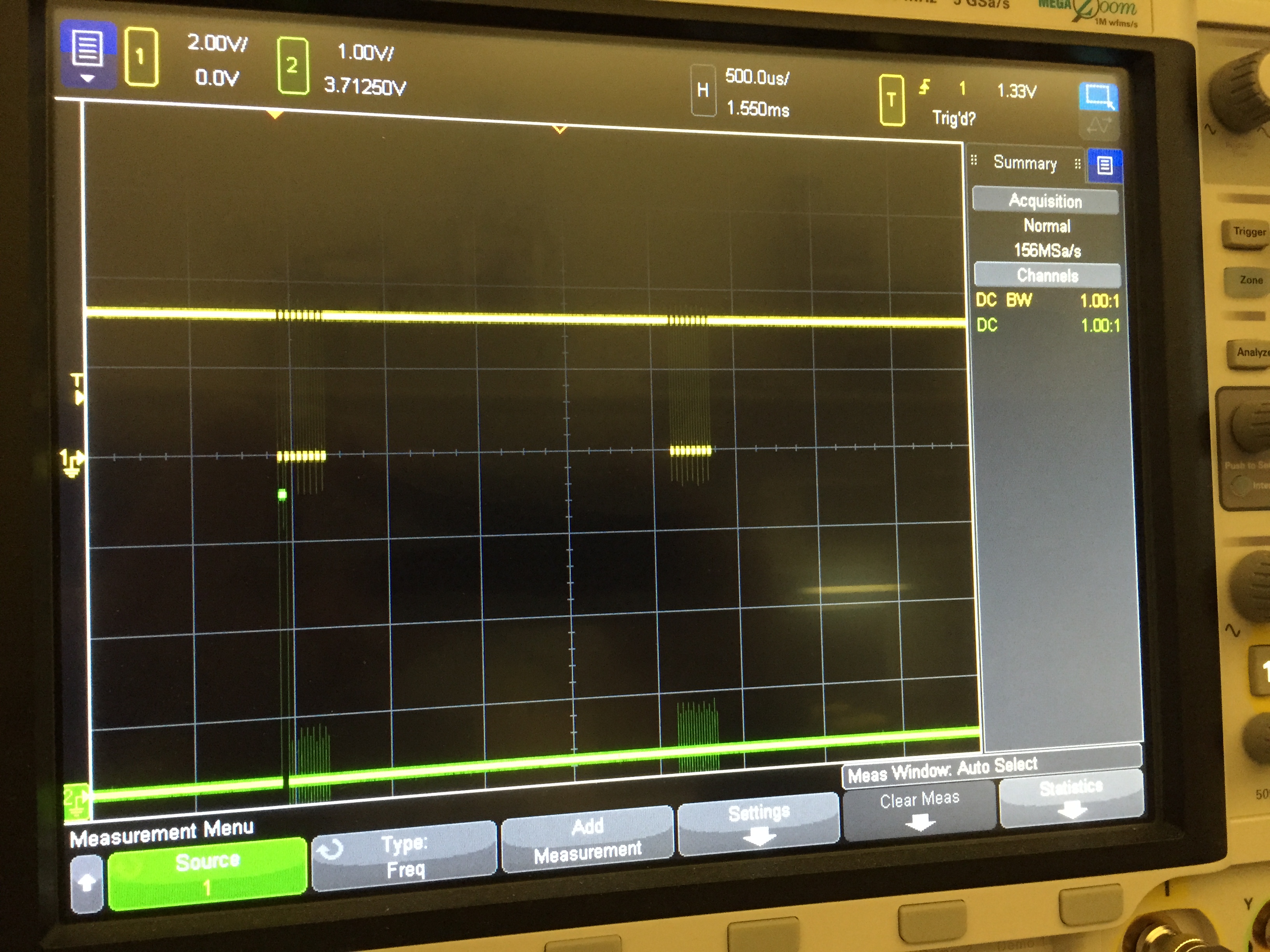
1: SCK, 2: MOSI (zoomed in)

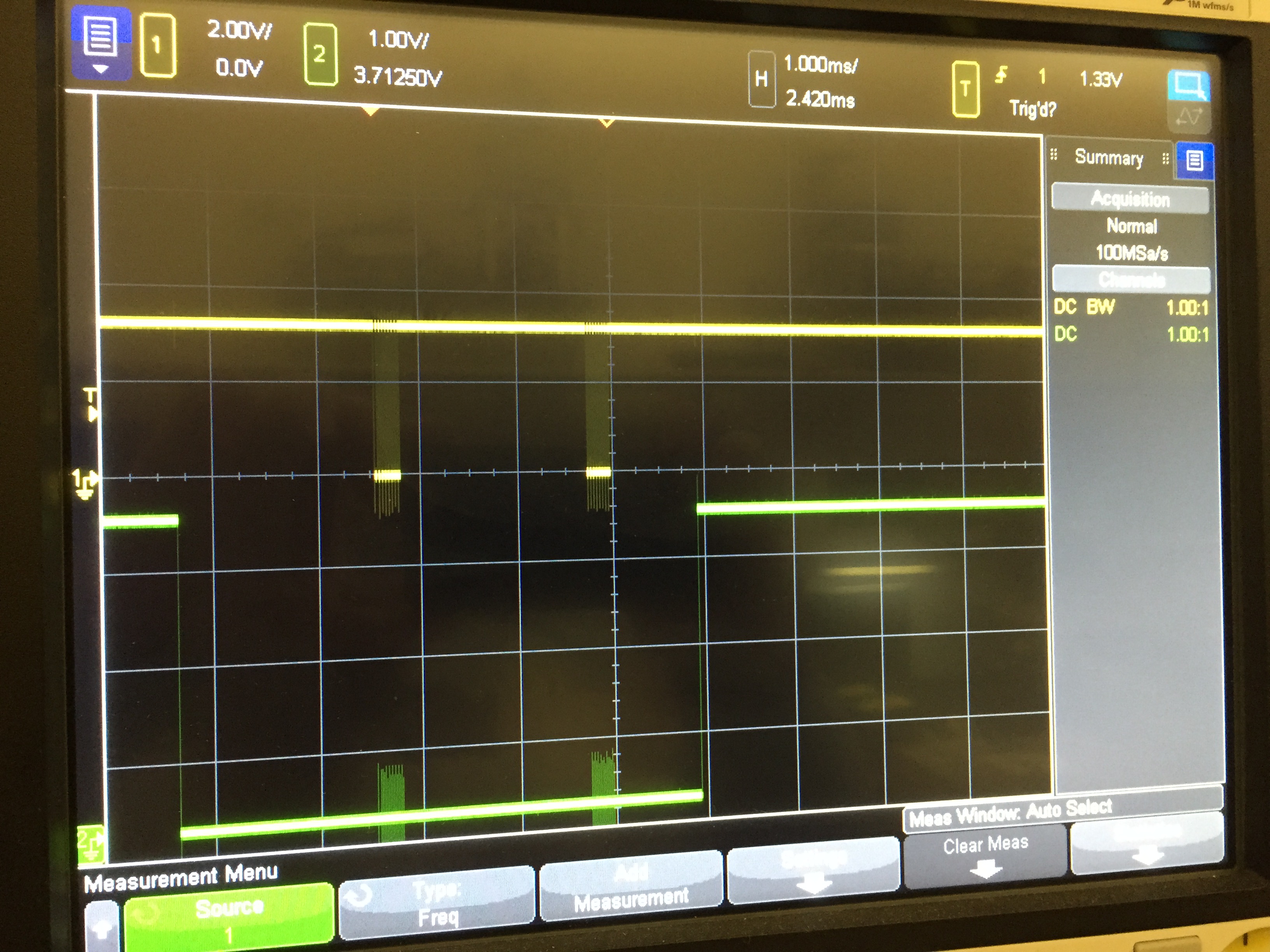
1: SCK, 2: /CS
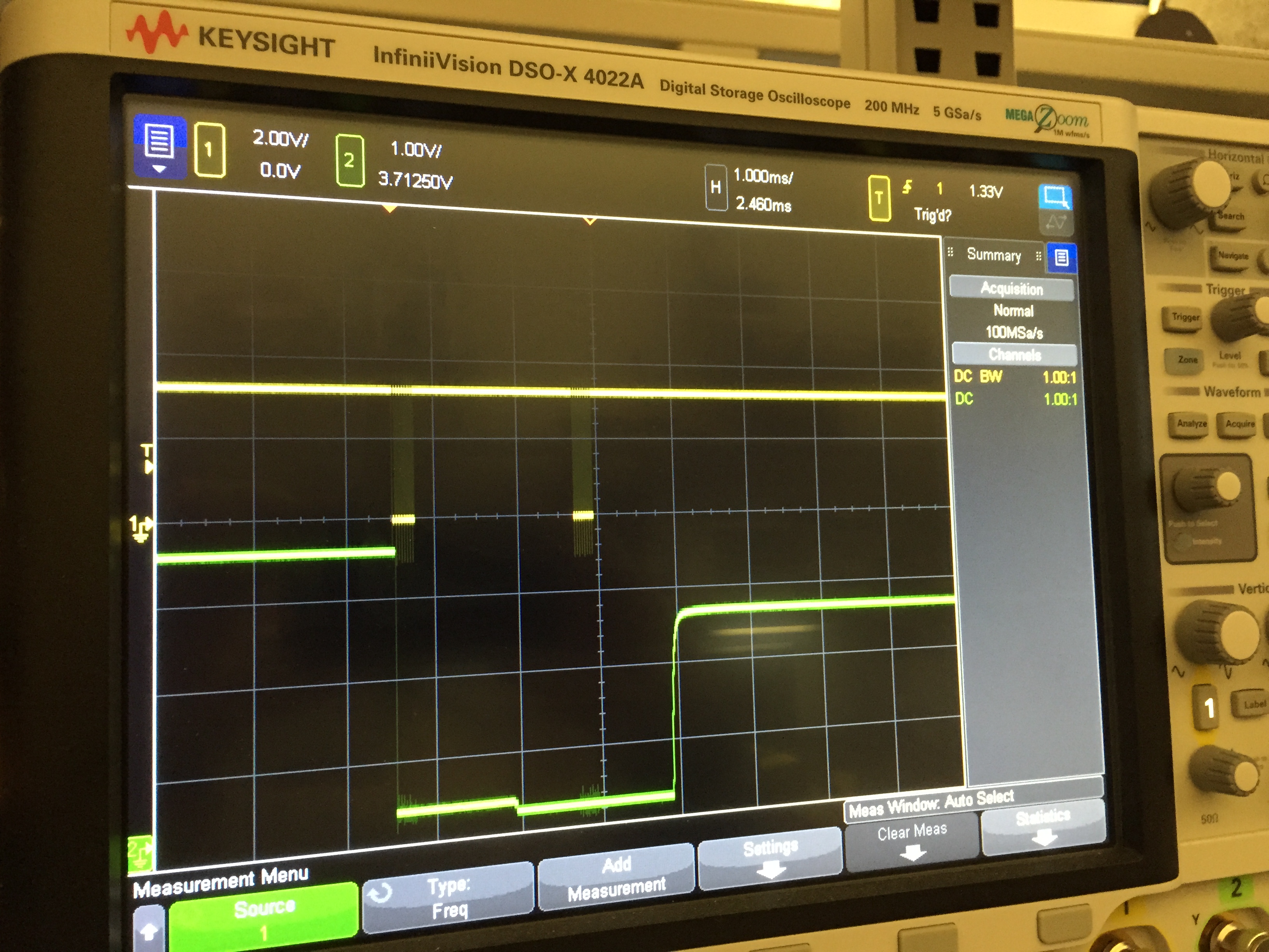
1: SCK, 2: MISO (failure 2)

1: SCK, 2: MISO (failure mode 2)
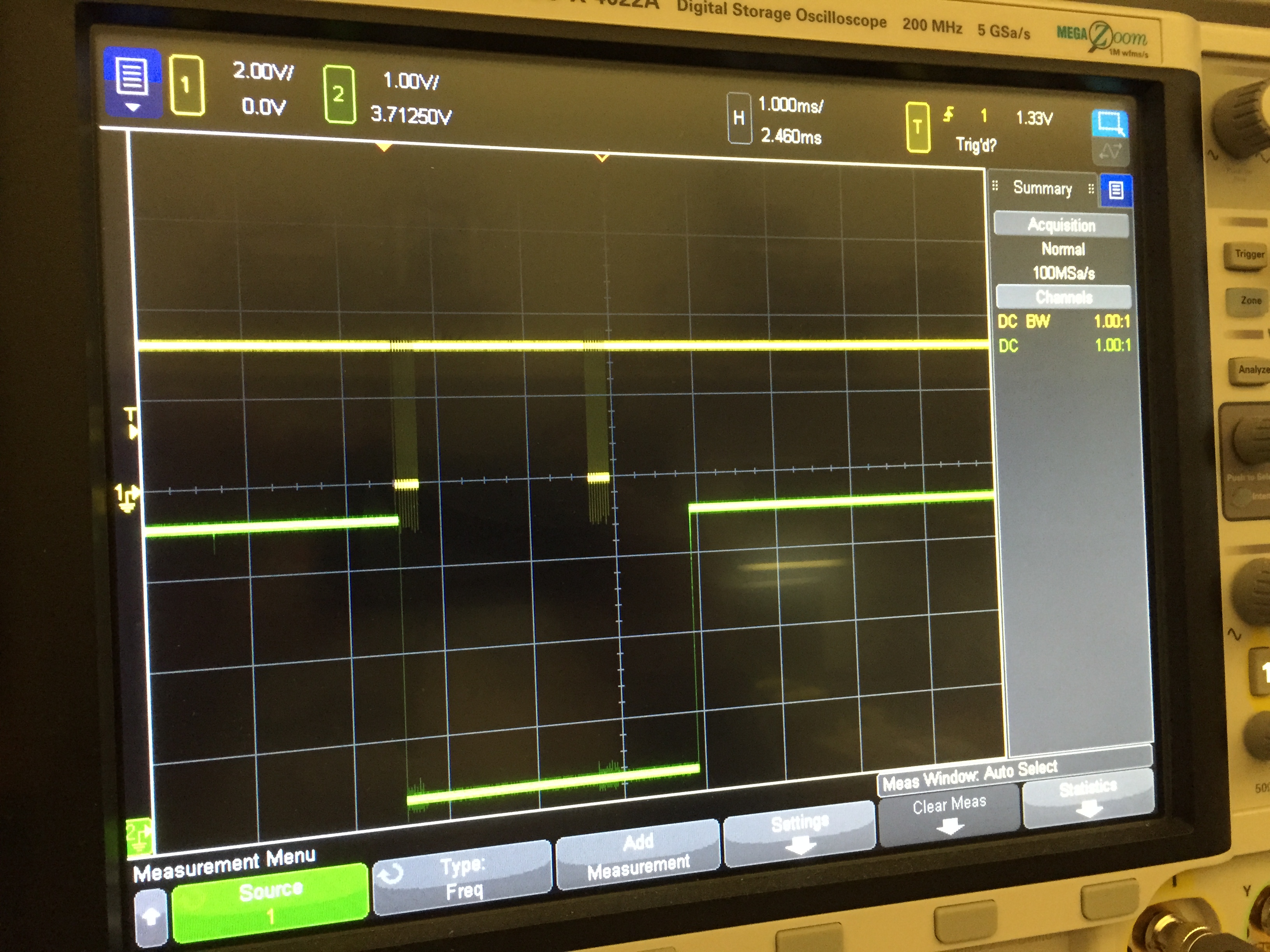
1: SCK, 2: MISO (failure mode 3)
Thanks in advance for any help you can give. This is for a trash sorting robot due in 1.5 weeks, and oddly we are only seeing this now.

