This thread has been locked.

If you have a related question, please click the "Ask a related question" button in the top right corner. The newly created question will be automatically linked to this question.

How to use MSP430 as clock instead of TDC7200 in TDC1000-TDC7200EVM?

Other Parts Discussed in Thread: TDC7200, TDC1000

I have TDC1000-TDC7200EVM with me and Its operating fine with default values and jumpers. I want to test it by using MSP430 MCU's clock by bypassing TDC7200 completely. My question is how to do this? What all jumpers I need to change and what all values in software GUI I need to change? Thanks.

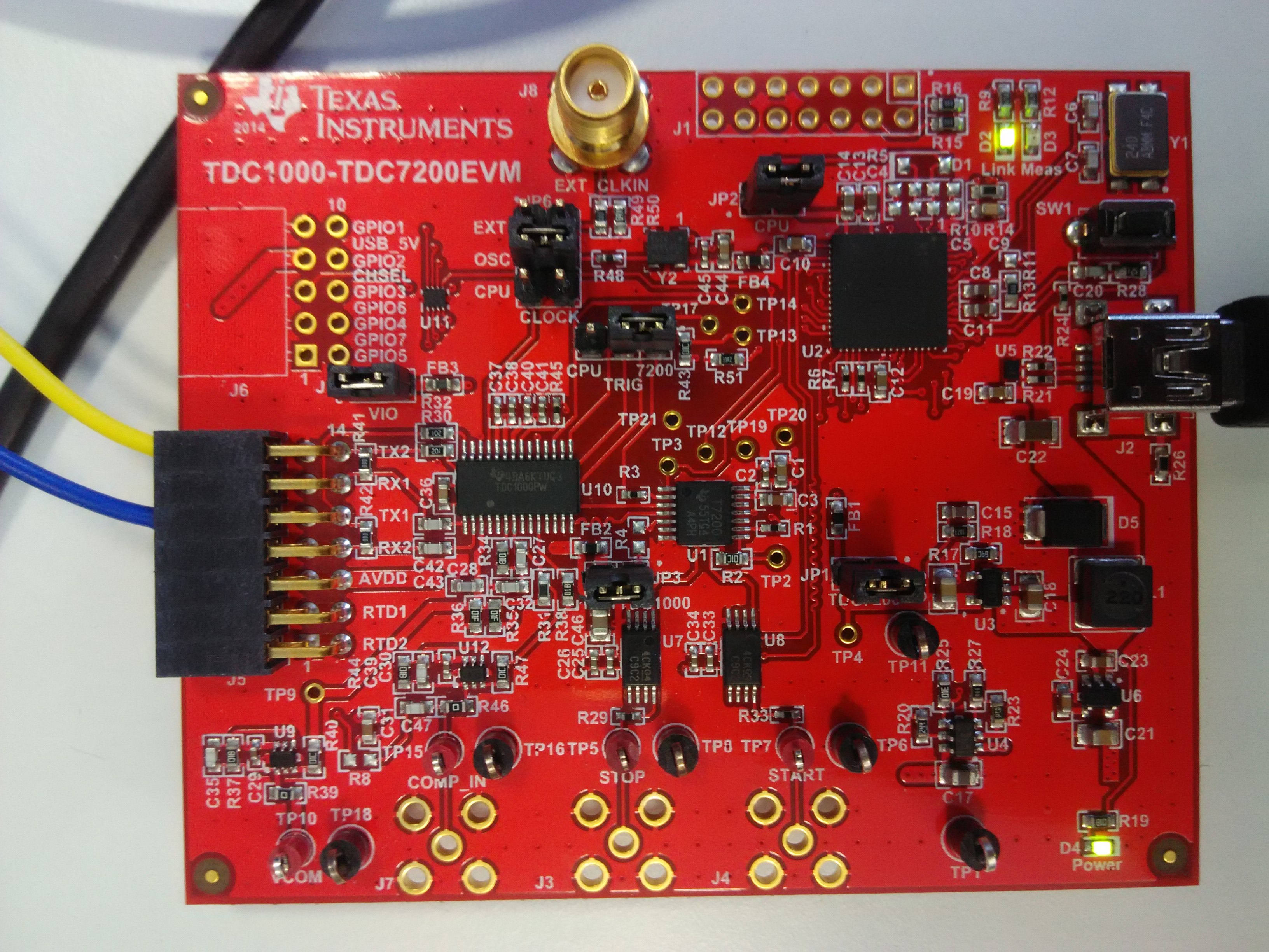
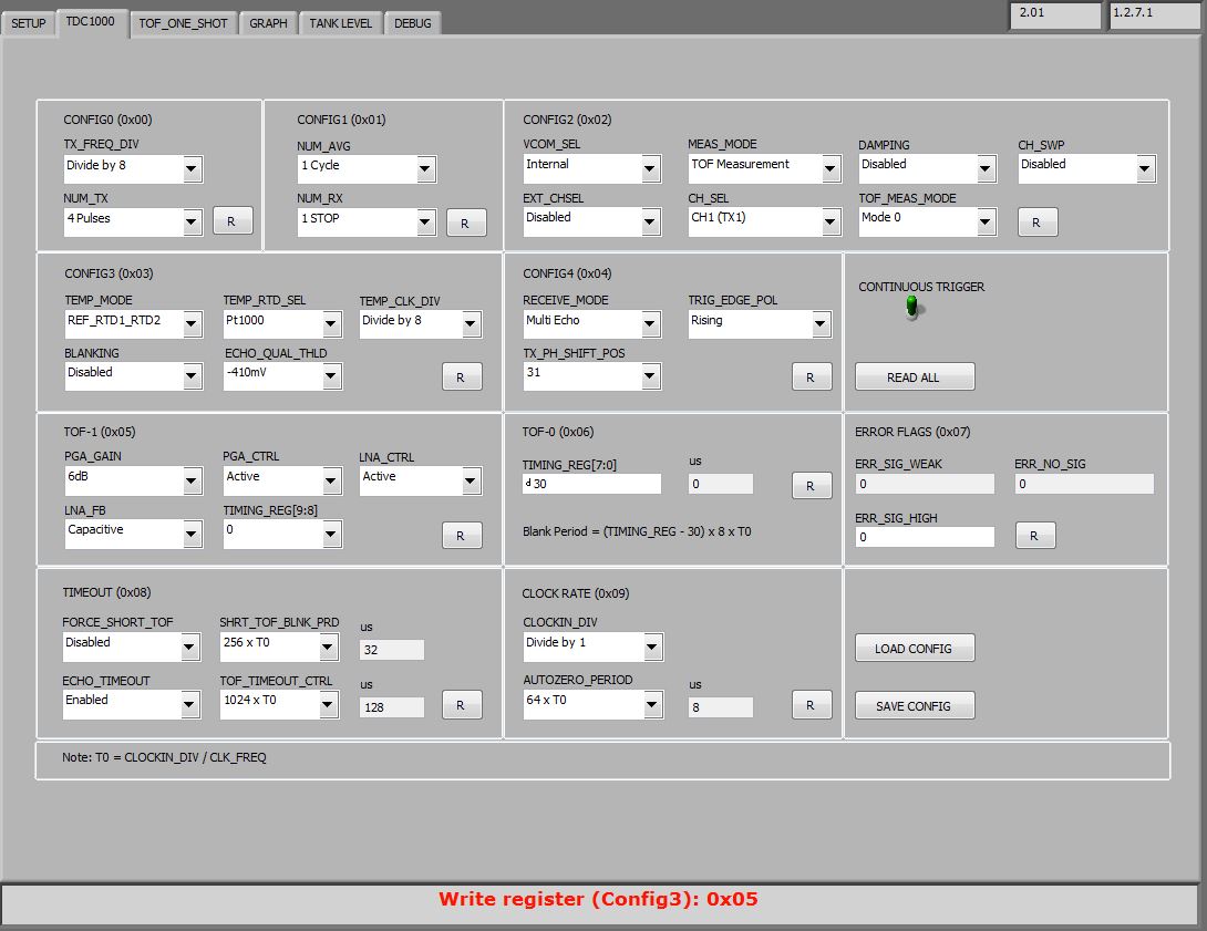
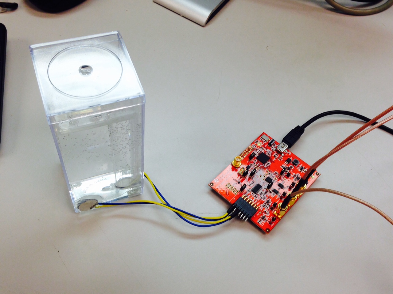
PS: To get status of jumpers on my EVM currently, Please find attached picture below.

  • Perry,

    To use MSP430 timer instead of TDC7200
    a) set the TRIG jumper to the CPU side. MSP430 Timer TA0 is already connected to the TDC1000 Start/Stop input.s
    b) Start the GUI and connect to the board. In the setup tab, select "Enable_MSP430TIMER_TDC" option on the GUI. Now TDC7200 tab should disappear and you should be able to do MSP430 based one shot measurement and graph.

    Thanks,
    Vishy
  • Vishy,

    Thanks. After excuting steps you just said, GUI started giving me wrong values. While height of liquid was 9.43cm approx, it was showing tank over flow. ToF using TDC7200 was approx 1,27,900 ns while using MSP430, it went over to 162,00,000 ns with same water amount. What does it mean? Or is this about register file which we load in TDC1000? Can you provide me that file if matters? Or is it affected by MSP430 firmware which I upgraded thorugh GUI?
  • Perry,
    I will test and get back to you soon.
    Thanks,
    Vishy
  • Sure, Vishy. I'll be waiting for your response.

  • Perry,

    I checked about this. The TDC1000 Register Settings is getting messed up when "Enable_MSP430Timer_TDC" is getting selected in the Setup tab of the GUI. So I have enclosed here two config files. You can load config files through TDC1000 Register tab page "Load Config" button. To get things working

    a) Save the enclosed config files

    b) Quit the GUI and Disconnect USB connection to board

    c) Reconnect board & restart GUI

    d) From TDC1000 Register page, select "Load Config" and load the enclosed TDC1000_Setup_MSP430TDC config file

    e) Now you should be able to do one and graph without error

    f) If you want to go back to use TDC7200, load the enclosed TDC1000_Setup_Default config file

    Thanks,

    Vishy

    TDC1000_Config0                         44
    TDC1000_Config1                         41
    TDC1000_Config2                         00
    TDC1000_Config3                         05
    TDC1000_Config4                         5F
    TDC1000_TOF-1                           40
    TDC1000_TOF-0                           1E
    TDC1000_Error_Flags                     00
    TDC1000_Timeout                         23
    TDC1000_Clock_Rate                      01
    TDC1000_Conts_Trigger                   00
    TDC7200_Config1                         02
    TDC7200_Config2                         40
    TDC7200_Interrupt_Status                00
    TDC7200_Interrupt_Mask                  07
    TDC7200_Coarse_Cntr_Ov_H                FF
    TDC7200_Coarse_Cntr_Ov_L                FF
    TDC7200_Clock_Cntr_Ov_H                 FF
    TDC7200_Clock_Cntr_Ov_L                 FF
    TDC7200_Clock_Cntr_Stop_Mask_H          00
    TDC7200_Clock_Cntr_Stop_Mask_L          00
    TRIGGER_UPDATE_FREQ                     0001
    TDC_AVG/STDEV_NUM_ELEMS                 000A
    SAVE_GRAPH_DATA_TO_FILE                 00
    FLOW_MODE_SELECT                        00
    Y-SCALE_CENTER                          00C8
    X-SCALE_RANGE                           0032
    MEASURE_RTD1                            00
    SAVE_RESULT_REGR_TO_FILE                00
    GRAPH_MULTI_STOPS                       00
    TDC_SELECT                              00
    TEMP_RTD_SELECT                         00
    TEMP_RTD_MODE                           01
    TEMP_AVG/STDEV_NUM_ELEMS                000A
    SAVE_TEMP_DATA                          00
    GRAPH_YMAX_DATA                         0000000000009BBB
    GRAPH_YMIN_DATA                         0000000000009A2B
    TDC1000-HV_DRV_EN1                      00
    TDC1000-HV_DRV_EN2                      00
    HV_DRV_EN1_Period                       001E
    HV_DRV_EN2_Period                       001E
    ENABLE_POWER_CYCLE                      00
    CLK_FREQ_(1-16MHz)                      8.000000
    CLK_SOURCE_SEL                          00
    CPU_CLK_FREQ                            05
    CPU_CLK_EN                              00
    TDC1000-HV_BST_PWR_EN                   00
    HV_BST_PWR_EN_Period                    0000
    FWD2REV_FLOW_DELAY                      0000
    TDC1000-IMPE_MATCH_EN                   00
    ENABLE_UART_STREAM                      00
    ENABLE_MSP430TIMER_TDC                  01

    TDC1000_Config0                         44
    TDC1000_Config1                         41
    TDC1000_Config2                         00
    TDC1000_Config3                         05
    TDC1000_Config4                         5F
    TDC1000_TOF-1                           40
    TDC1000_TOF-0                           1E
    TDC1000_Error_Flags                     00
    TDC1000_Timeout                         23
    TDC1000_Clock_Rate                      01
    TDC1000_Conts_Trigger                   00
    TDC7200_Config1                         02
    TDC7200_Config2                         40
    TDC7200_Interrupt_Status                00
    TDC7200_Interrupt_Mask                  07
    TDC7200_Coarse_Cntr_Ov_H                FF
    TDC7200_Coarse_Cntr_Ov_L                FF
    TDC7200_Clock_Cntr_Ov_H                 FF
    TDC7200_Clock_Cntr_Ov_L                 FF
    TDC7200_Clock_Cntr_Stop_Mask_H          00
    TDC7200_Clock_Cntr_Stop_Mask_L          00
    TRIGGER_UPDATE_FREQ                     0001
    TDC_AVG/STDEV_NUM_ELEMS                 000A
    SAVE_GRAPH_DATA_TO_FILE                 00
    FLOW_MODE_SELECT                        00
    Y-SCALE_CENTER                          0032
    X-SCALE_RANGE                           0032
    MEASURE_RTD1                            00
    SAVE_RESULT_REGR_TO_FILE                00
    GRAPH_MULTI_STOPS                       00
    TDC_SELECT                              00
    TEMP_RTD_SELECT                         00
    TEMP_RTD_MODE                           01
    TEMP_AVG/STDEV_NUM_ELEMS                000A
    SAVE_TEMP_DATA                          00
    GRAPH_YMAX_DATA                         00000000004C4B40
    GRAPH_YMIN_DATA                         0000000000030D40
    TDC1000-HV_DRV_EN1                      00
    TDC1000-HV_DRV_EN2                      00
    HV_DRV_EN1_Period                       001E
    HV_DRV_EN2_Period                       001E
    ENABLE_POWER_CYCLE                      00
    CLK_FREQ_(1-16MHz)                      8.000000
    CLK_SOURCE_SEL                          00
    CPU_CLK_FREQ                            05
    CPU_CLK_EN                              00
    TDC1000-HV_BST_PWR_EN                   00
    HV_BST_PWR_EN_Period                    0000
    FWD2REV_FLOW_DELAY                      0000
    TDC1000-IMPE_MATCH_EN                   00
    ENABLE_UART_STREAM                      00
    ENABLE_MSP430TIMER_TDC                  00

  • Thanks, Vishy.

    I'll try the solution suggested by you and will revert to you here.
  • Hi I tried files provided by you but I am facing few issues:

    a) JP5 is set to CPU.

    b) I am using *TDC1000_Setup_MSP430TDC.txt* load file.(attached also)

    TDC1000_Config0                         44
    TDC1000_Config1                         41
    TDC1000_Config2                         00
    TDC1000_Config3                         05
    TDC1000_Config4                         5F
    TDC1000_TOF-1                           40
    TDC1000_TOF-0                           1E
    TDC1000_Error_Flags                     00
    TDC1000_Timeout                         23
    TDC1000_Clock_Rate                      01
    TDC1000_Conts_Trigger                   00
    TDC7200_Config1                         02
    TDC7200_Config2                         40
    TDC7200_Interrupt_Status                00
    TDC7200_Interrupt_Mask                  07
    TDC7200_Coarse_Cntr_Ov_H                FF
    TDC7200_Coarse_Cntr_Ov_L                FF
    TDC7200_Clock_Cntr_Ov_H                 FF
    TDC7200_Clock_Cntr_Ov_L                 FF
    TDC7200_Clock_Cntr_Stop_Mask_H          00
    TDC7200_Clock_Cntr_Stop_Mask_L          00
    TRIGGER_UPDATE_FREQ                     0001
    TDC_AVG/STDEV_NUM_ELEMS                 000A
    SAVE_GRAPH_DATA_TO_FILE                 00
    FLOW_MODE_SELECT                        00
    Y-SCALE_CENTER                          00C8
    X-SCALE_RANGE                           0032
    MEASURE_RTD1                            00
    SAVE_RESULT_REGR_TO_FILE                00
    GRAPH_MULTI_STOPS                       00
    TDC_SELECT                              00
    TEMP_RTD_SELECT                         00
    TEMP_RTD_MODE                           01
    TEMP_AVG/STDEV_NUM_ELEMS                000A
    SAVE_TEMP_DATA                          00
    GRAPH_YMAX_DATA                         0000000000009BBB
    GRAPH_YMIN_DATA                         0000000000009A2B
    TDC1000-HV_DRV_EN1                      00
    TDC1000-HV_DRV_EN2                      00
    HV_DRV_EN1_Period                       001E
    HV_DRV_EN2_Period                       001E
    ENABLE_POWER_CYCLE                      00
    CLK_FREQ_(1-16MHz)                      8.000000
    CLK_SOURCE_SEL                          00
    CPU_CLK_FREQ                            05
    CPU_CLK_EN                              00
    TDC1000-HV_BST_PWR_EN                   00
    HV_BST_PWR_EN_Period                    0000
    FWD2REV_FLOW_DELAY                      0000
    TDC1000-IMPE_MATCH_EN                   00
    ENABLE_UART_STREAM                      00
    ENABLE_MSP430TIMER_TDC                  01

    c) Actual level of water is approx. 5.3 cm (photo attached of container) as shown while using TDC7200(also confirmed using scale)

    d) Bypassing TDC7200 shows water level approx 796 cm. (Please find screen shots attached of 'Graph' tab and 'Tank Level'tab)

    I also tried playing around with register values by understanding them like, Increasing tx pulses, adjusting threshold voltage value, adjusting timeout, adjusting PGA/LNA etc but It didn't worked out. It just keep showing wrong values. Please look into matter and revert on this.

  • Did you look at the START (J4 or TP7), STOP (J3 or TP5) and COMPIN_OUT (J7 or TP15) signals on the scope? You have to adjust and optimize the register settings looking at these signals. The register settings I provided are for the test cell I used with and it cannot apply directly to your setup.
    While monitoring the Start/Stop/Compin signal from the register tab, make sure "continuous trigger" is set to Green. Then as you change the echo-qual-thld or PGA gain, you can see the effect on the scope. Please refer to the app note www.ti.com/.../snaa270.pdf
    (Section 3.2.2).
    Thanks.
  • Here's the register settings I start with (note: echo qual threshold is set at the lowest -1500mv & continuous trigger is Green)

    Corresponding to above settings, here's what I see on the scope (yellow CH1 is start, green CH2 is stop, purple CH3 is COMP_IN & note there's no stop pulse corresponding to the echo is seen as the threshold is set way out)

    I changed echo threshold level to -410mV in the register settings 

    Here's a scope shot corresponding to this change (note the stop pulse corresponding to the echo)

    I change echo qual threshold to -220mv in the register settings below 

    Scope shot for this change (a wider stop pulse corresponding to a lower threshold)

    Here's a screen shot of the graphing & tank level (note MSP430 uses 12MHz as timer clock, so 1 timer tick corresponds to about 83.33ns and this is the step size of the variations)

    Thanks

  • I show my setup again below - note this time clock jumper JP6 is set to CPU clock

    In the GUI setup tab, I choose 2MHz CPU clock source as shown below

    Note I am still using MSP430 as the TDC timer above. Now in the register settings, I update TX_FREQ_DIV to 2 so transducer burst is at 1MHz, with all the other register settings remain the same

    Scope capture of the signals corresponding to this is shown below. Note TOF is approximately 140.4us below

    Graph and tank measurements below

    Thanks.

  • And here's the config file I used for MSP430TDC + CPUCLK2MHz configuration

    TDC1000_Config0                         04
    TDC1000_Config1                         41
    TDC1000_Config2                         00
    TDC1000_Config3                         05
    TDC1000_Config4                         5F
    TDC1000_TOF-1                           40
    TDC1000_TOF-0                           1E
    TDC1000_Error_Flags                     00
    TDC1000_Timeout                         23
    TDC1000_Clock_Rate                      01
    TDC1000_Conts_Trigger                   01
    TDC7200_Config1                         02
    TDC7200_Config2                         40
    TDC7200_Interrupt_Status                00
    TDC7200_Interrupt_Mask                  07
    TDC7200_Coarse_Cntr_Ov_H                FF
    TDC7200_Coarse_Cntr_Ov_L                FF
    TDC7200_Clock_Cntr_Ov_H                 FF
    TDC7200_Clock_Cntr_Ov_L                 FF
    TDC7200_Clock_Cntr_Stop_Mask_H          00
    TDC7200_Clock_Cntr_Stop_Mask_L          00
    TRIGGER_UPDATE_FREQ                     0001
    TDC_AVG/STDEV_NUM_ELEMS                 000A
    SAVE_GRAPH_DATA_TO_FILE                 00
    FLOW_MODE_SELECT                        00
    Y-SCALE_CENTER                          00C8
    X-SCALE_RANGE                           0032
    MEASURE_RTD1                            00
    SAVE_RESULT_REGR_TO_FILE                00
    GRAPH_MULTI_STOPS                       00
    TDC_SELECT                              00
    TEMP_RTD_SELECT                         00
    TEMP_RTD_MODE                           01
    TEMP_AVG/STDEV_NUM_ELEMS                000A
    SAVE_TEMP_DATA                          00
    GRAPH_YMAX_DATA                         000000000002244F
    GRAPH_YMIN_DATA                         00000000000222BF
    TDC1000-HV_DRV_EN1                      00
    TDC1000-HV_DRV_EN2                      00
    HV_DRV_EN1_Period                       001E
    HV_DRV_EN2_Period                       001E
    ENABLE_POWER_CYCLE                      00
    CLK_FREQ_(1-16MHz)                      2.000000
    CLK_SOURCE_SEL                          03
    CPU_CLK_FREQ                            0C
    CPU_CLK_EN                              01
    TDC1000-HV_BST_PWR_EN                   00
    HV_BST_PWR_EN_Period                    0000
    FWD2REV_FLOW_DELAY                      0000
    TDC1000-IMPE_MATCH_EN                   00
    ENABLE_UART_STREAM                      00
    ENABLE_MSP430TIMER_TDC                  01

  • Hi

    Thanks for insights. I noticed all START, STOP signals on my scope here and accordingly changed TDC1000's register values according to my setup and I am able to run application bypassing TDC7200 and using CPU_CLK. However, there are 2 issues I encountered:
    1. I was able to see START and STOP signals on my scope but not able to get COMP_IN signal on scope (may be due to some configuration/ specs of my scope). (I will also post screenshot of my scope here soon)
    2. I am able to sense fluid from approx. ~1 cm to ~2 cm using one specified set of register values and from ~2.5 cm to ~20cm using other specified set of register values. I was not able to figure out a particular set of register values, with which I can sense fluid level in my setup from ~1 cm to ~20 cm approx. continuously.

    Please project your views on it.

    PS: I noticed that your GUI is not capable of showing water level below that ~2.5 cm graphically, however in 'graph' tab, even lower ToF can be noticed but that doesn't get reflected on 'Tank Level' tab.