Hi
We assume the following system.
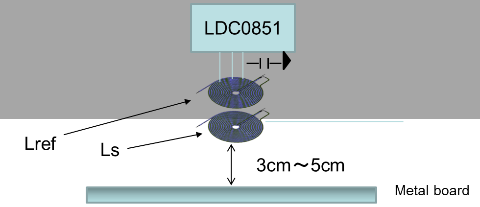
CASE:1
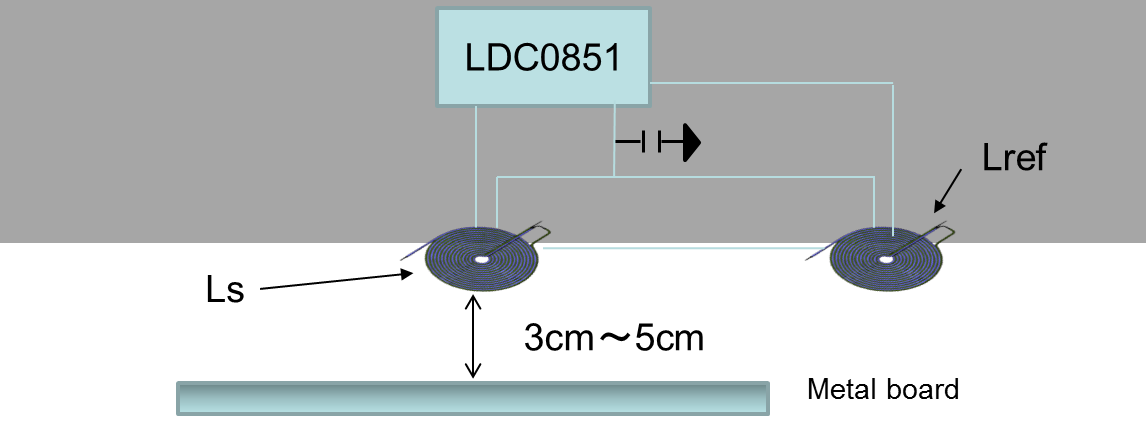
CASE:2
The purpose of this system is just to detect the metal board.
Distance between target metal board and sensor is about 3cm ~5cm.
So, we need information how to design coil. Could you please advise us?
1. What do you think which coil placement case is better, case1 or case2?
2. We have LDC0851EVM and LDCCOILEVM. So, we want to start evaluation.
What do you think which coil size and capacitance should be chosen?
3. We can use LDC calculation tool (excel sheet).
If possible, could you feedback how to design coils as example?
Best Regards