This thread has been locked.

If you have a related question, please click the "Ask a related question" button in the top right corner. The newly created question will be automatically linked to this question.

The PADC Drifting problem..................

Other Parts Discussed in Thread: PGA900

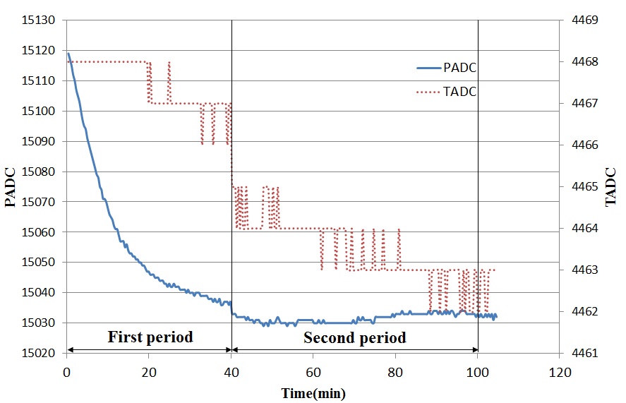
The following figure is the result of PGA900 EVM built-in EXTERNAL BRIDGE with constant temperature at 23.5C and setting resistance at 246.484 Ω. The first period of TADC variation is from 4468 to 4465 within 0~40 min, respectively. There are 3 difference divisions. When time is range of 40 to 100 min in second period, the difference division is also 3, which result is the same with previously. But the variation of PADC in first stage is decreased from 15120 to 15035(85 difference division), and second stage is almost keeping at 15030. Theoretically, the second stage of PADC value should be decreased the same difference division value from 15035 to 14950. If a single TADC value can’t correspond to a single PADC, even after the compensation, the accuracy of load cell can’t be increased.

  1. Why the second stage is keeping a constant value when TADC is keeping changed? Is that normal?
  2. Is the PADC drift can be controlled at a minimum through the register setting or a circuit layout?
  3. How to evaluate the basic variation divisions in PGA900?  Then, I will realize how much difference division is normal.
  4. What is the highest accuracy through compensation of the PGA900?


  • Hi,

    Can you provide some more details about your test configuration?

    • What are your PADC and TADC settings? Gain settings, are you using the internal pull-ups on those pins, 16 or 24 bit ADC, etc. 
    • Are you forcing a constant temperature to the PGA900 or to the entire EVM? Is the temperature on the resistive bridge being maintained? 
    • Is this TADC data from the internal temp sensor or are your using an external sensor tied to the VINTP and VINTN pins? 

  • What are your PADC and TADC settings? Gain settings, are you using the internal pull-ups on those pins, 16 or 24 bit ADC, etc.
    the following setting was copied from PGA900_cfg.c file:

    M0_ConfigClock(CLK_1MHZ);
    DAC_Config(DAC_ENABLE, DAC_RATIOMETRIC_MODE_DISABLE,DAC_GAIN_4V | B_4_20MA_DISABLE | DACCAP_DISABLE);
    CONFIG_ALPWR(POWER_UP_PT_PGA_FD | ADC_EN_VREF | GATE_CTRL_SD_DISABLE);
    AMUX_CONFIG(TEST_MUX_DAC_EN | TEST_MUX_P_EN | TEST_MUX_T_EN);
    AFE_CFG_CONFIG(PGAIN_CLOSE);
    ADC_Pchannel_Config(ADC_ENABLE | ADC_ENABLE_16BIT | ADC_DECI_RATE_128US | ADC_INT_RATE_EVERY_SAMPLE, 0x1E); //PGAIN=200
    ADC_Tchannel_Config(ADC_ENABLE | ADC_ENABLE_16BIT | ADC_DECI_RATE_128US | ADC_INT_RATE_EVERY_SAMPLE, T_GAIN_5_V_V);
    ADC_Config(ADC_CFG_1_ADC_ENABLE); 
    TEMP_MUX_CONFIG(VTEMP_INT|ITEMP_CTRL_OFF);
    COM_MCU_TO_DIF_B=0;
    AFEDIAG_CFG_CONFIG(DIS_R_SD|DIS_R_TEMP);


    Are you forcing a constant temperature to the PGA900 or to the entire EVM? Is the temperature on the resistive bridge being maintained?

    Yes, I am really sure the entire EVM and load cell (resistive bridge) were forced at a constant temperature value within a chamber.


    Is this TADC data from the internal temp sensor or are your using an external sensor tied to the VINTP and VINTN pins?

    The TADC data is from internal temp sensor. In order to make sure the temperature is on steady state, I provide another Figure as follows.

    after the 6 hours, the temperature is stable at 7682, but PADC was still changing with times. 


  • Hi,

    You are using very large PADC gain with a resistive bridge that has some temperature drift that can definitely be seen with that much gain.

    With the conditions you provided, a PADC code of about 8600 is about 3.281 mV differential on the input. Your final PADC code of about 8565 would be about 3.267mV. That means you have a drift of about 15 uV at the input.

    The AD5252 has a potentiometer drift of 650 ppm/C per wiper. In a worse case situation the resistance in the bridge can potentially change as much as 1300 ppm/C. In this worst case situation, you can see a drift of 40uV across the differential inputs of the ADC for a single 1 C change in temperature. 

    So in summary the PADC drift you are seeing is most likely just a very small amount of of temperature change of the bridge. Even something as small as 0.5C is enough to cause the amounts of PADC drift you are seeing. This also is not factoring in the drift of the rest of the simulated bridge.

    To confirm this, we can see that your TADC code is changing from about 7670 to 7682. Converting that to Degrees C is a change in 0.5 C, which is about as much as I suspected above for the amount of drift on the bridge. 

  • Dear Matt Sullivan:


    I am really Thanks for your detail response so fast.

    You mentioned “the TADC code is changing from about 7670 to 7682. Converting that to Degrees C is a change in 0.5 C” for total time period you are right, but after 6 hours the TADC is situated a steady state condition, so the PADC should be kept a constant value with minimum drift. In terms of temperature, the TADC have changed about 2 divisions in range of 6 to 14 hours, converting that to Degrees C is a change in 0.1 C, therefore the drift should be control in 4uV. Anyway, through this Figure, the PADC is still changing when TADC keep a constant value. Maybe the PADC have basic drift whatever the temperature at any constant value? I just want know the accuracy if this chip, please help me to define it, thanks for your help.

  • The part exhibiting the drift is the resistive bridge, not the PGA900 itself. That is why you are seeing different amounts of drift in the ADC at different times. I'm sure the die temperatures of each of the devices are slightly different at different times and you are slowly seeing the change occurring over time. 

  • Thanks Matthew
    I will perform a experiment to supply the power into resistive bridge directly without PGA900EVM.
    And detect the variation of temperature, Vout as well as Vin to define the drift.
    Thanks