Hi,
We want to design a 3-wire transmitter, but the supply current for our sensor needs to be higher than the maximum PGA900 excitation current. The inputs to our circuit are the following ones:
- Positive supply (+12V DC)
- Negative supply (GND for the positive supply)
- Signal output (4..20mA)
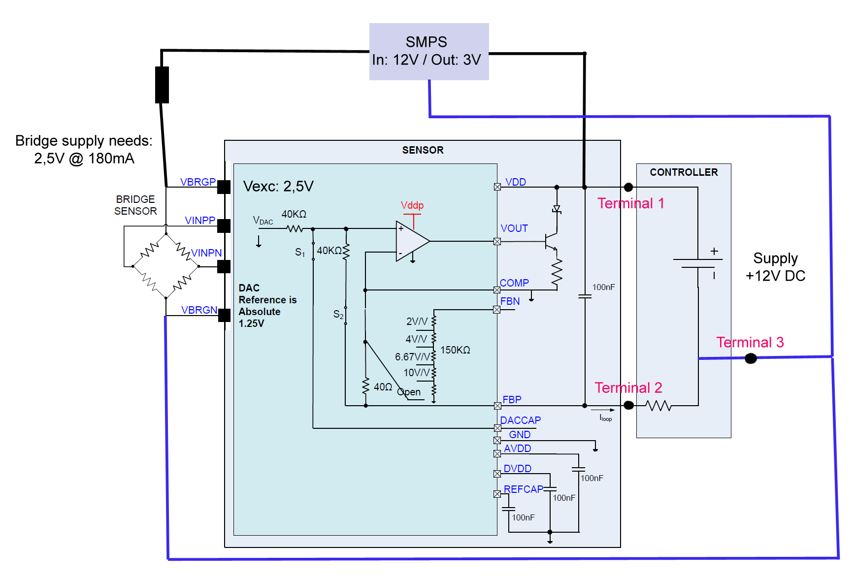
We have tried to follow the TI’s reference circuit but our problem is that our bridge sensor is a catalytic gas bead and it needs about 180mA of excitacion current. TI’s design is made for 2-wire transmitters and ir our case, we could work with a 3-wire connection because we have a direct connection to the supply GND. We will like to separete the 4..20mA signal from the supply line return path.
Please, see attached file with a circuit proposal. We are not sure about the current return paths. Where should we connect the return path (GND) for the SMPS converter and for the VBRGN terminal?
We will appreciate any help you can give us. Thank you very much.