This thread has been locked.

If you have a related question, please click the "Ask a related question" button in the top right corner. The newly created question will be automatically linked to this question.

Accuracy of LMT89 chip

Other Parts Discussed in Thread: LMT88, LMT89, MSP430G2553
We are a medical device manufacturer who makes a blood analyzer that in its original design used the TI LMT88 for ambient temperature sensing.

In a more recent pilot manufacturing run, we updated that chip with the LMT89, which according to its datasheet has superior performance (in terms of accuracy of the temperature measurements) when compared to the LMT88. It was simple for us to do since the LMT89 and LMT88 have the same pin-out and usage, just that the LMT89 is supposed to be more accurate.

However, when we ran through a verification exercise after getting the first few assembled devices, we saw that the LMT89 performance is not as stated in its datasheet and not much better at all compared to the LMT88. The LMT89 datasheet states that all measurements should be within ± 1.5C.
Here is a table summarizing the data we collected using 5 LMT88 chips, and 5 LMT89 chips. We do have more detailed data available, but this is a good starting point.
LMT88
Room temperature (C) Minimum (C) Maximum (C) Average (C) Variance SD
23 25.85 28.35 27.184 0.99293 0.9964587297
21 24.18 27.1 25.766 1.16723 1.080384191
LMT89
Room temperature (C) Minimum (C) Maximum (C) Average (C) Variance SD
23 22.92 27.1 25.346 2.66033 1.631051808
21 22.08 25.01 23.674 1.35158 1.162574729


We are trying to better understand why there is both this variability across individual chips, and also why the measurements are off like this, more than what the LMT89 datasheet describes. Would someone from TI be able to comment on this?
 
Michal
  • Hi Michal,

    Let me help you with this but let me ask some questions:

    • How are you testing the devices? What test environment are you using?
    • Are you using any reference thermometers or temperature references?
    • How are you reading the analog output voltage to convert to temperature?

    -Michael Wong

  • Hi Michael,

    Thanks for the quick reply.

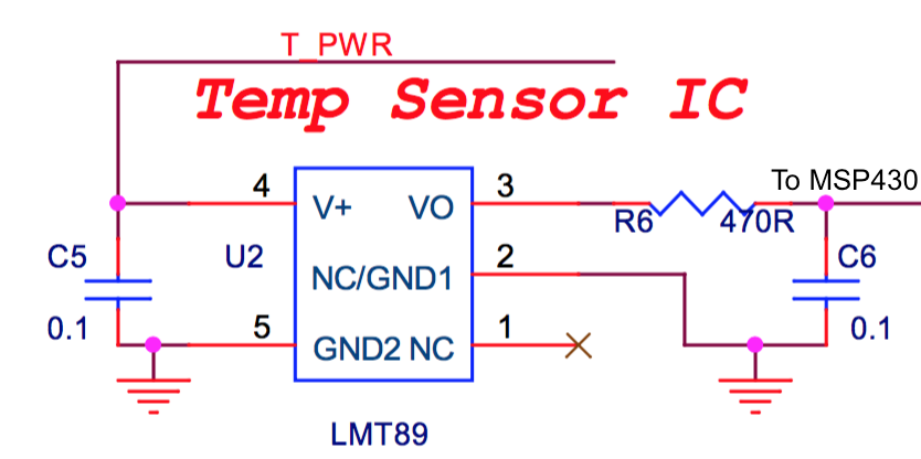
    We are using the LMT88 / LMT89 chips directly in the board of our device, and it was wired up as recommended in their datasheets. Please see the annotated sub-schematic below. The output is connected to the ADC of a MSP430 chip. T_PWR is connected to one of the output pins on the MSP430. We then take the detected voltage value and apply the conversion formula in the datasheet, which is actually the same for LMT88 and LMT89 chips.

    Yes, we use a calibrated hygrometer in our production facility, which is re-calibrated regularly. That is a ISO 13485 certified facility.

    Please let me know if you have any more questions.

    Thanks,

    Michal

  • Hi Michal,

    Your schematic is correct and I cannot see any problems with your method of interfacing with the MSP430. The ADC in the MSP430 series of microcontrollers come in a variety of flavors, can you describe the ADC characteristics (# of bits, reference voltage level, type, etc) or provide the MSP430 part number?

    Just to do some more trouble shooting, can you measure the output of the LMT88 and LMT89 with a voltmeter and verify if they match up to Table 1 in their respective datasheets. Next compare this voltage measurement to the voltage reading from the ADC and see if both readings match.

    -Michael Wong
  • Hi Michael,
    Sure, here is the information you requested:
    -Number of bits: 10 bits (using ADC10 on MSP430)
    -Reference voltage level: 2.5V
    -MSP430 part number: MSP430G2553IPW20R
    Please let me know if I missed anything. Also, we will hopefully this coming week collect a larger dataset across more ambient temperatures, and we will make sure to measure the voltage output out of the LMT89 as well. We had not done it in the previous dataset because we tried to keep our devices as they would be used by customers, meaning with the casing closed.
    Thanks,
    Michal
  • Hi Michal,

    The LMT88/89 can only sink current they cannot source it. If your try to pull current out of the output the output will go high thus indicating a colder temperature but that is not your case as you are reading consistently hotter temperatures. You may want to try a pullup resistor to VDD to see if that is the problem. I think the cause of your issue is probably the ADC input sample and hold. We have had to increase the acquisition time and lengthen the time between conversions for a similar device in order to make the device work properly. You may also need to play around with C6. If you sample too fast it causes the charge on the cap to deplete as the temperature sensor output does not have enough time to recover.

    Take care,
  • Hi Michael and Emma,

    On the firmware side we are already using maximum sample and hold time of 64 cycles while the clock source we are using for ADC operations is the internal digitally controlled oscillator at 1 Mhz. The clock divider is set to ADC10DIV_3 and changing it to ADC10DIV_7 also doesn't change the output by much. Can you tell us what is the response time needed for the LMT89 chip to yield accurate results. Does the LMT89 chip need a ew seconds to stabilise and start giving accurate values. Also what is the accuracy we should expect from the LMT89 chip especially at temperatures between 20C and 30C.
    Also since our circuit has no issues, do you suggest any changes in the clock source or sampling time?
  • Hi Soumil,

    I just looked at the MSP430G2553 family user's guide and you can increase the sample and hold time to 1024 cycles. Is your firmware constantly sampling the LMT89 output? If so it may be too fast, have you tried creating an interrupt (or delay) that enables every second or so and in that interrupt calls an ADC sample?

    The LMT89 does not take a long time to settle to the final temperature value, maybe a few seconds at most. From Figure 1 in the datasheet, the accuracy between 20C and 30C is +/-1.8C.

    -Michael Wong
  • Hi Michael,

    The sample and hold time can be increased to 1024 cycles when using ADC12 and not using ADC10 according to the user guide. Since we are using ADC10, the maximum sample and hold time can be set to only 64 cycles. Please correct me if i am wrong. 

    Our firmware is not constantly sampling the LMT89 output. The sampling time we use is minimum of 400 ms and maximum of 1 second depending on our specific application. Do you think we should read the temperature values minimum of every 2 seconds and not less than that? 

    Also do you think any analog noise is getting added up during the ADC sampling?

    Another thing to add is that if we keep measuring the ADC value of the temperature sensor for around 20 seconds every 1 second then we seem to get values within the accuracy mentioned in the datasheet. Any reason for that ?

  • Hi Soumil,

    The schematic of your system and your sampling times seem good to me. I am beginning to think your problems may stem from the error specs of the ADC10. Quickly looking over the MSP430G2553 user's guide shows special calibration values for the internal ADC that nulls the offset and gain errors. The user's guide only mentions specifically a ADC12 example but shows ADC10 is available as well, you may have to ask the MSP430 on the details on that. I believe getting rid of those ADC errors will improve the accuracy significantly.

    -Michael Wong
  • Hi Michael,

    Are you talking about using the calibration equations for the ADC output which involves gain and offset factors. If that is the case then we have already started using these and are using the same equations as mentioned in this link
    e2e.ti.com/.../382021

    I hope this is the correct way of doing it. Secondly do you think using ADC12 instead of ADC10 might be helpful in this case or it wont make much difference?
  • Hi Soumil,

    That is correct. I just took another look at the MSP430G2553 datasheet. Is it possible for you to change the voltage reference to 1.5V instead of 2.5V? If this does not work try the ADC12 peripheral.

    -Michael Wong
  • Hi Michael,

    Do you have any update on this?