This thread has been locked.

If you have a related question, please click the "Ask a related question" button in the top right corner. The newly created question will be automatically linked to this question.

Temperature Measurement with TDC1000-GASEVM

Other Parts Discussed in Thread: TDC1000, TDC7200

Hello,

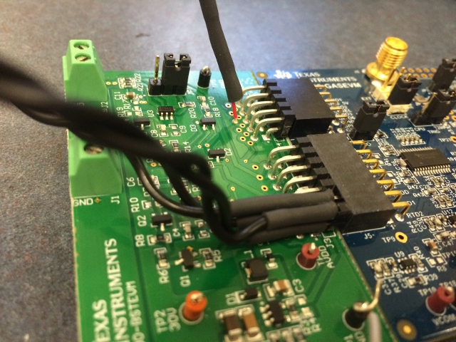
I am currently working to get my GASEVM board to measure temperature values from 2 PT1000 RTDs (www.digikey.ca/.../1014573). In order to do this I took out the headers on the booster board which were plugged into the RTD1/RTD2 slots. I wired up my RTDs and plugged them in. The setup can be seen below:

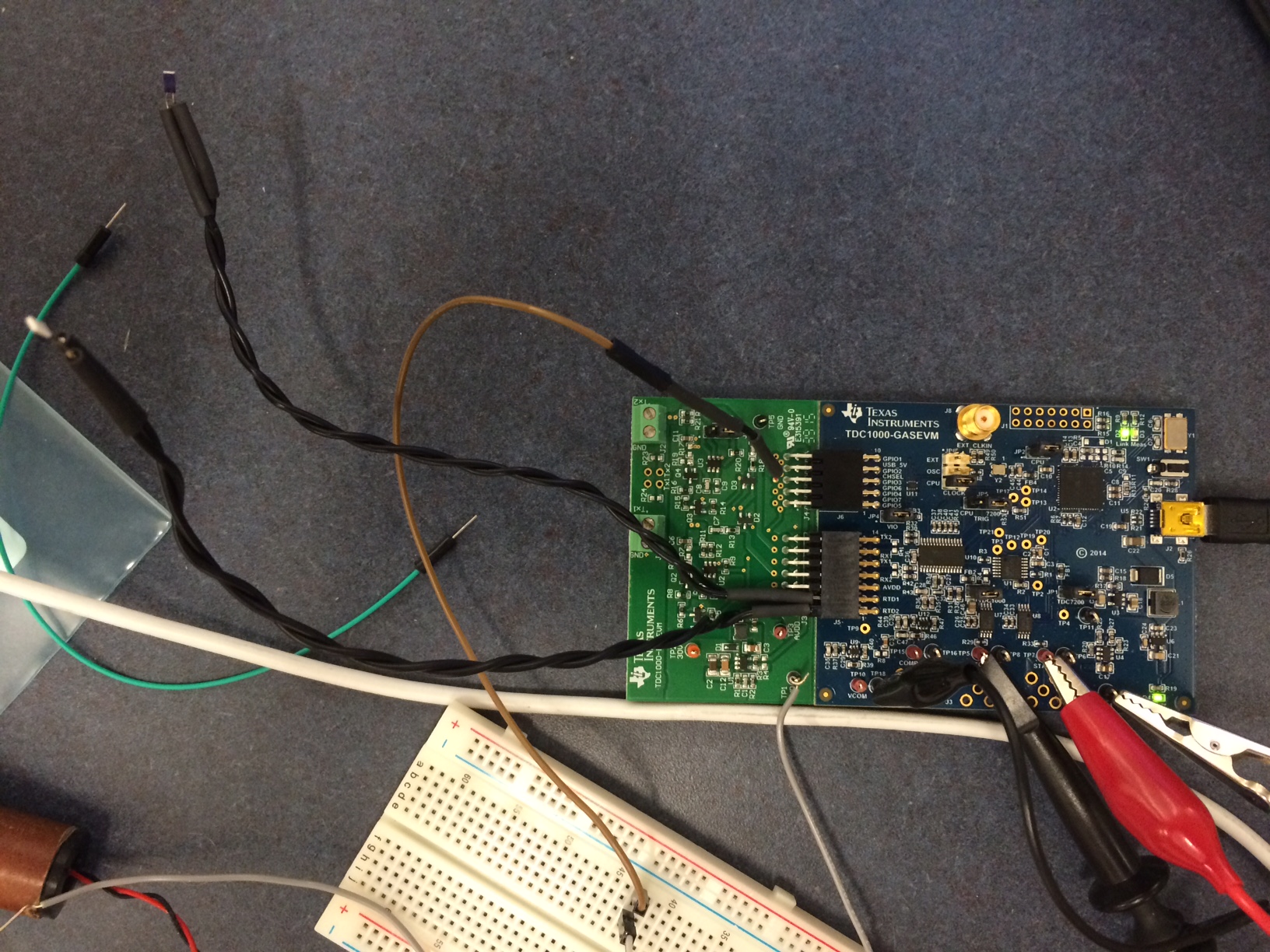
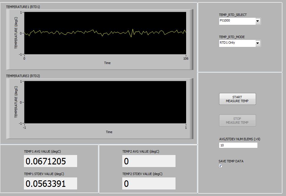
Now I have these wired into a Raspberry Pi to transfer the TOF/resistance data over UART. This works well with the TOF data but I am having issues when I try to measure temperature. The following is a picture of the data being transferred to the raspberry pi while doing a temperature measurement:

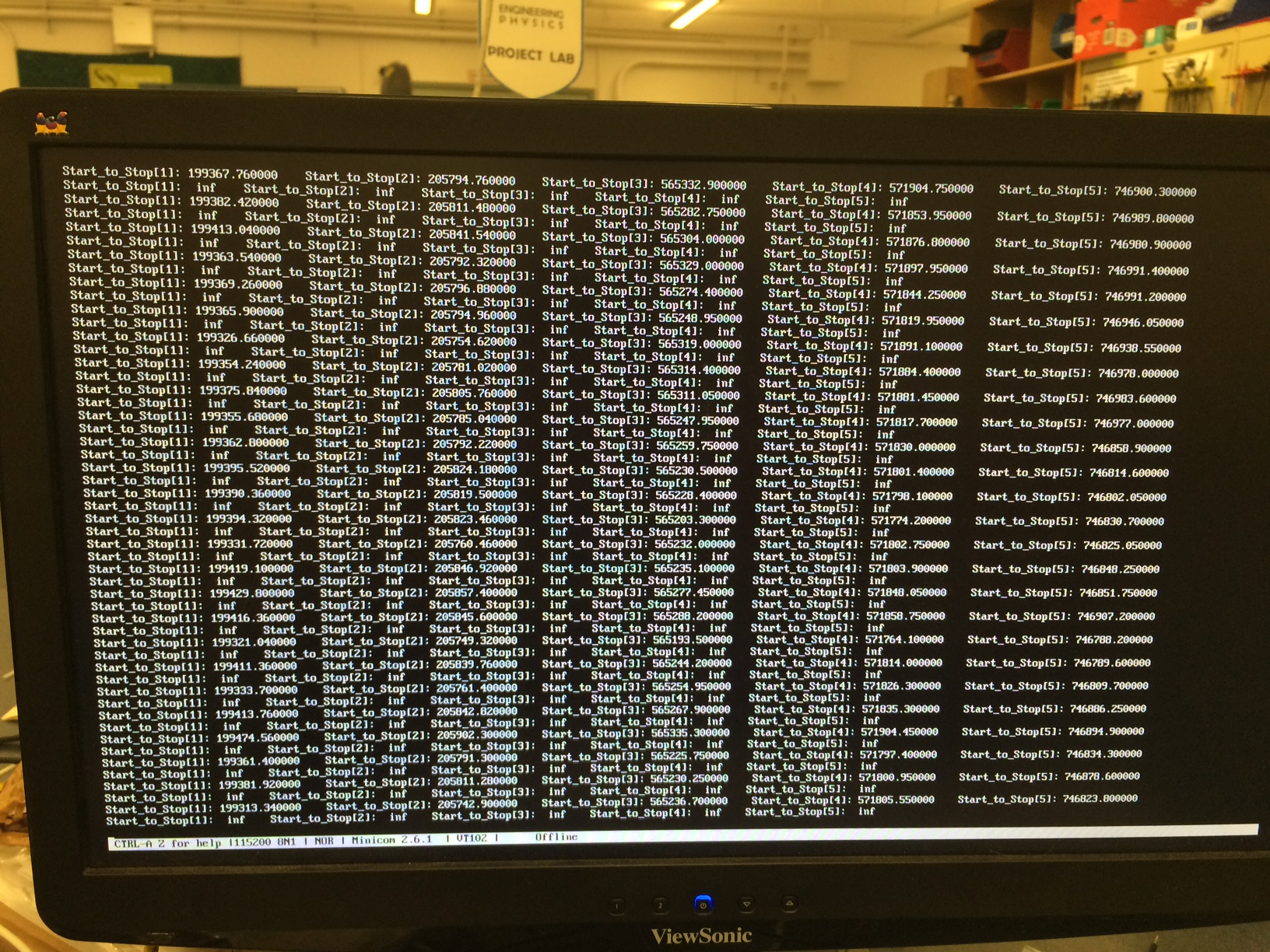
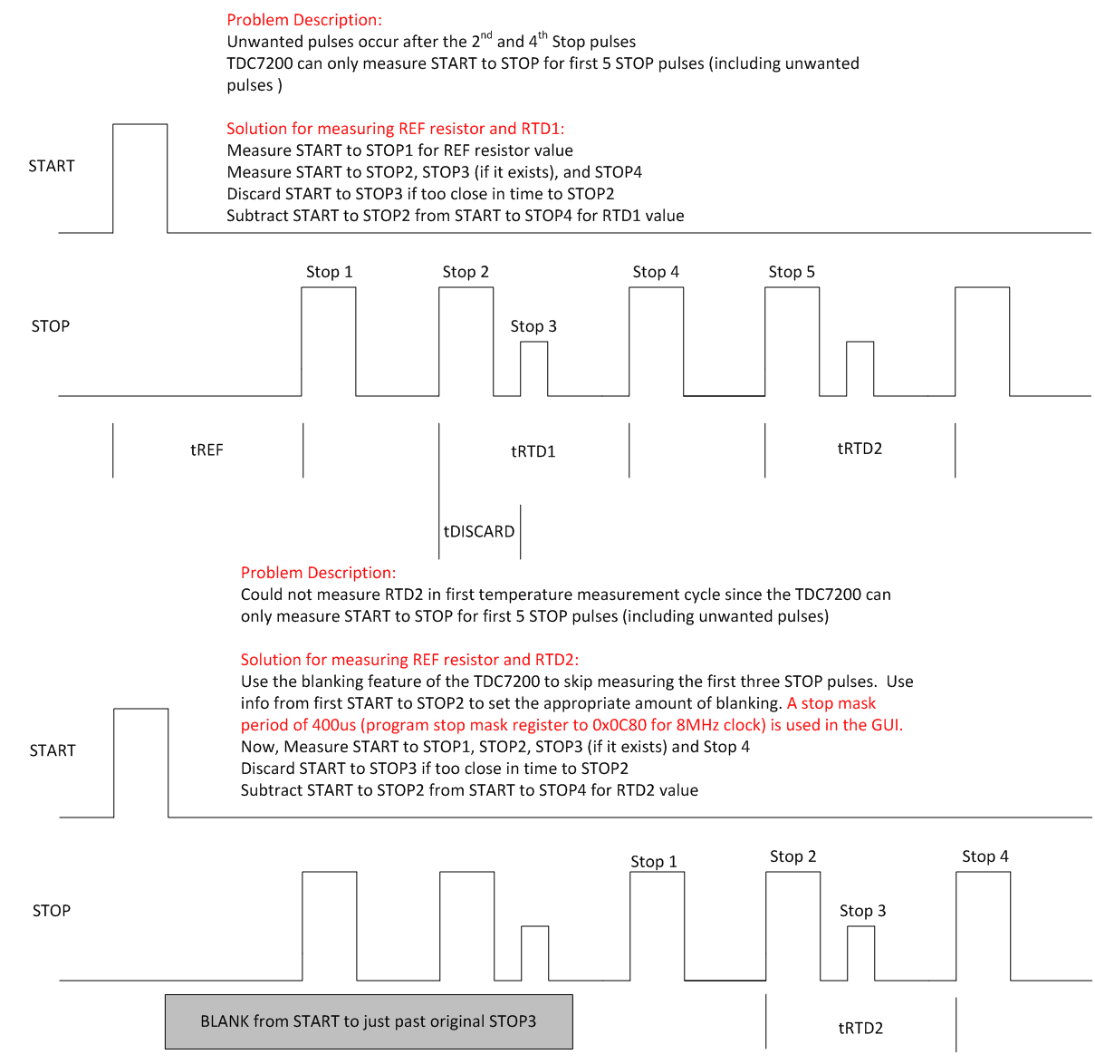
Now I am having two issues with this. The first is obviously the issue of the values "inf" being passed over on every second measurement sequence. I do not know why this is happening. The second issue is with the values I am getting during the other sequences. Using the TDC1000 datasheet I have understood that the resistance of RTD1 can be determined by finding the time interval of start_to_stop[3] - start_to_stop[2], and RTD2 from start_to_stop[5] - start_to_stop[4]. Now the problem I am having is with start_to_stop[2]/[4]. These values are extremely soon after [1]/[3] respectively, and when looking at the stop signals on my oscilloscope I don't know where they are coming from(see below):

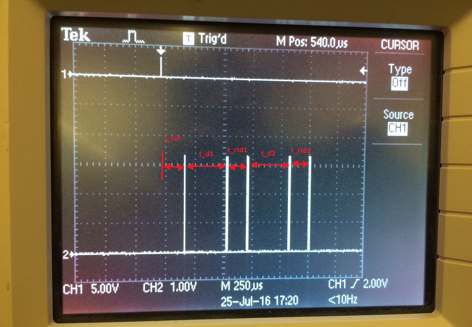
as can be seen above, the stop signals which I measure from the oscilloscope give me very reasonable temperature measurements, but the 5 stop signals being provided by the TDC7200 do not correlate with these.

I have read through the application note on RTD measurements, and have noticed it talk about these short timing signals, but I do not know how I can get rid of them. I will continue trying to work through it but any information on this would be very helpful.

note: One possible solution I could think of is to change the firmware to do two separate measurements? the first, taking the first 5 values to find t_rtd1 and then the second one I could blank the first 4 stop signals so that I could determine t_rtd2?

Thanks,

Russell

  • This app note explains in Section 6 software solution to measure RTD1. See especially example Table 2 remarks. That's the work around implemented in GUI for measuring RTD1.

    The enclosed figure below gives you an explanation of the RTD measurement issue and how we have addressed it in the GUI using a software filter along with the stop mask feature of TDC7200.

    In summary, we do the measurement in two steps:

    -        In step1, we do the RTD1 measurement (which was also explained in the app note above).

    -        In step2, we apply masking (from start to just past stop3) and measure again to get RTD2. In the GUI, stop mask register (0x12) is programmed to 0x0C80  for a stop mask period of 400us when using 8MHz clock.


    Thanks,

    Vishy

  • Hi Vishy,

    Thank you for the response. I have looked at that application note previously, but did not realize this was already executed in the GUI due to a chip issue; I will work out a way to execute this with my current raspberry pi setup. I do have a few concerns/questions with what is happening though:

    1) While doing the temperature measurement as I described in my initial question, the GUI was not recording any temperature data. Every time I pressed "Start Measure Temp" data would be sent over UART but the Temperature tab in the GUI would not record anything. If the solution listed in that application note is executed in the GUI, should it not still record the data?

    2) Why am I getting a line of "inf" values for every second measurement sequence? does it have to do with the fact that the TDC7200 can only record 5 STOP pulses, yet the added unwanted pulses create 7? Also, is there any way to correct this so that I can at least pick up the value of RTD1 every measurement period? if not, I can just lower my trigger time from 200ms to 100ms which would effectively do the same thing.

    Thanks,

    Russell

  • GUI should record the data. I just tested with TDC1000-TDC7200EVM (not GASEVM but shouldn't matter for this issue). I connected a 1kohm resistor between RTD1 and GND so to see a reading close to 0degC. I show below the settings I choose. I could save the RTD1 temperature data in a file as well.

    Thanks,

    Vishy

  • Regarding your question 2: If I understand right, the raspberry pi setup is mainly to receive data over UART from TDC1000GASEVM and is not controlling the TDC1000. Is that right? In that case, first make sure GUI is correctly displaying RTD1 (and RTD2) data. Then you have to implement in your MCU what the GUI is doing.

    Thanks,
    Vishy