This thread has been locked.

If you have a related question, please click the "Ask a related question" button in the top right corner. The newly created question will be automatically linked to this question.

LDC1000: Rp and L value read error

Other Parts Discussed in Thread: LDC0851

Hi team,

One of my customer is using the LDC1000 as a switch in the server rack application to detect the mechanical switch closing. The coil design is exported from the Webench and it is a square coil similar to what is shown below.

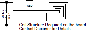
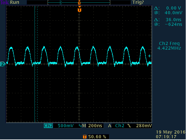
It results in an inductance of 5.8uH. They have used a NP10 470pF capacitor and are able to see the oscillations around 3.75MHz across the tank. When they bring the metal switch close to the coil, we see that the frequency is changing(increases). The Rp value is set to the widest range possible. The capacitor between the CFA and CFB is 22pF.

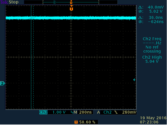
The issue here is that the proximity count and the Fcount are all zeros. The DRDY bit is always high signifying that the data conversion has not started. When we probe the CFB pin, we see a DC voltage of 5V and CFA pin shows 1V DC. I read in the guide that these pins must show some oscillations; we are unable to see it. The status register 0x20 reads 0xF0. 

Can you tell me how to proceed with the debugging? Below is the register writes that they perform.

-          Reg 0x1: 0x0E (We tried 0x00 as well)

-          Reg 0x2: 0x3F

-          Reg 0x4: 0x17

-          Reg 0xB: 0x01

-          Tried settings Reg 0x03 from 0x01 to 0xFF as well


  • Hello Mahesh,
    from the application that you described, it appears the LDC1000 is not the best device choice. I recommend looking into using the LDC0851 for a switch detection application.

    If you decide to go with the LDC1000, please attach scope plots of the CFA/CFB waveforms and of the sensor pin.

  • Hi Ben,

    We had rigorously promoted the LDC1000 for the earlier projects(before LDC0851 was RTMed) and he is familiar with its versatility.

    The CFA pin settles to a DC voltage of 1.5V and the CFB pin settles at 5V. The sensor pin shows sine wave oscillation at ~4.2MHz with the target present.

    Below are the waveforms attached

    Tank One end:

    CFA:

    CFB:

    The filter capacitor used in 10pF and they earlier had tried with a 22pF also.

  • Hello Mahesh,
    it appears that the RP of your sensor is too low. This is the reason why the CFA/CFB is saturated, and the oscillation amplitude is only 1V, even though the register is set for 4V. Please verify that the sensor RP is within the specified limits.
  • Hi Ben,
    They designed the coil using Webench designer. Here is the exact coil details:
    Trace width: 0.102 mm
    Trace Separation: 0.114 mm
    Total Turns per Layer: 9
    Number of Layers: 4
    Copper Thickness: 1 Oz
    Layer to Layer Separation: 0.07 mm
    Coil outer diameter: 6.25 mm
    The calculated Rp as per Webench: ~ 1.9 k which is withing range.

    One thing to note here is that the coil is not on the bottom most layer rather one layer above it. It is etched on 4 layers from the penultimate layer. Is this a concern?
  • The coil can be placed on any PCB layers (placing it on the layers near the target will result in marginally better sensing range). Did you add a copper cut-out on the other layers? A copper cut-out of at least 1.5x coil diameter on all empty layers is recommended.

    The RP of 1.9k should be ok, but please also check that it is still in range in presence of your metal target.
  • Hi Ben,
    In case the Rp value is not in range when the target comes near, can we add a series resistance with the coil to effectively increase the Rp? Will this approach work?
    I think there is no cut out on other layers above the coil.
  • Hi Mahesh,
    if there is no GND cut-out on the other layers, then your performance and sensing range will be seriously impacted. The GND flood acts as a second target which is much closer to the coil than the intended target. I recommend re-spinning the PCB and ensure a GND cut-out on the other layers.