This thread has been locked.

If you have a related question, please click the "Ask a related question" button in the top right corner. The newly created question will be automatically linked to this question.

LM73 Read data abnormal

Other Parts Discussed in Thread: LM73

Customer feedback a issue, as below:

The temp read value is abnormal when Configuration Register =0x40 , if set as 0x50, the value is normal.

Why setting alert polarity than cause a error temp value? 

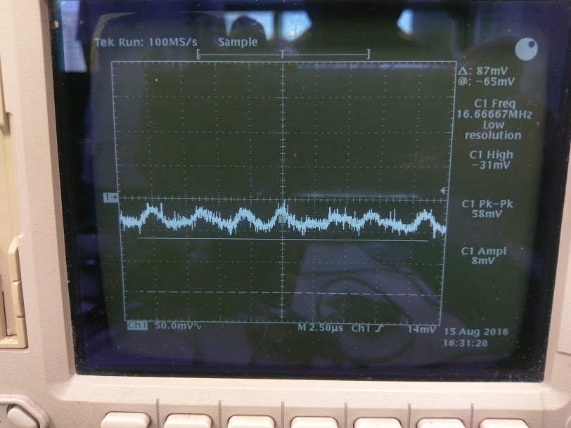
Also we have check the power noise cause a temperature error, power supply ripple is about 80mV, it seems ok.

Case 1:

Read 00 : 191 (5f c0)     //Temp Data Register, abnormal temp as 191 degree

Read 01 : 40            //Configuration Register , 40 = Alert pin Active-low

Read 02 : 7f e0        // T-high Upper-limit register,  255 degree (7f e0)

Read 03 : 80 00       // T-low Lower-limit register,  -256 degree (80 00)

Read 04 : 09            // Control/Status register, bit3=1, Alert pin = 1,

Read 07 : 01 90       // Identification register


Case 2: set Configuration Register =0x50 (Active-high)

Read 00 : 1c e0     //get temper = 57 (1c e0)  temperature is ok of 57 degree

Read 01 : 50         //Configuration Register , 50 = Alert pin Active-high

Read 02 : 7f e0    //get T-high = 255 degree  (7f e0)

Read 03 : 80 00   // get T-low = -256 degree (80 00)

Read 04 : 01        // Control/Status register, bit3=0, Alert pin = 0,

Read 07 : 01 90

  • Hi Jason,

    80mV of supply noise is rather marginally high. Do you have a bulk bypass capacitor such as 1uF or larger on your board? If not I would suggest adding one.

    It seems you have the part setup properly can you share your schematic?

    How is the ALERT pin connected?

    Can you probe the ALERT and send a scope photo?

    Take care,

  • Dear Emmy:

    After check the Alert pin, there is a pull high design with MOS-FET as an on/off switch function.

    If remove it, the temp reading value is normal.

    >>But, Cu want to know, why alert pin with upon design achieve a error temp.

    Is there any design recommend for Alert output, thanks for your help.

  • Hi Jason,

    The ALERT output is only designed to sink 3mA. What size is the pull-up resistor and to what voltage is it going to? It's best if you can share the cu schematic with me I only need to know how they plan to connect the ALERT output. They may need to add another stage to signal condition the drive for the MOSFET. I can't recommend anything on the limited information you have given me.

    Also check for ground loops and make sure all the grounds are connected together.

    Take care,

  • Hi Jason,

    Did you find out what the issue was?

    Take care,
  • Dear Emmy:

    thank you, after check, there is a MOSFET as switch function on the output of alert pin.

    If remove this MOSFET, the reading data is abnormal.  Now, Cu using a BJT as a switch buffer of MOSFET.

    Why alert pin can't as a switch control directly? thanks a lot.   

  • Hi Jason,

    In the configuration regiter, D6, D1, and D0 are reserved for test purposes. Please do not enable these bits. It must be kept zero at all the time. If you want to set the alert polarity, the configuration register value should be 0x10 not 0x40.

    Hope this helps!

    Aaron
  • Correct information.

    If remove this MOSFET, the reading data is normal.

  • Hi Jason,

    Are you trying to pull the ALERT pin above the VDD of the LM73? If so that will not work. Can you send us your schematic? We need to understand how you are connecting the MOSFET before we can comment further.

    Thanks!