This thread has been locked.

If you have a related question, please click the "Ask a related question" button in the top right corner. The newly created question will be automatically linked to this question.

Trouble reading TDC7200EVM registers using Energia

Other Parts Discussed in Thread: TDC7200EVM, ENERGIA, TDC7200, TDC1000

I am using the TDC7200EVM with the MSP430F5529LP. I have the GUI working fine, but I am trying to read the data using Energia code, which uses Arduino coding and SPI library. So far I have not been able to get anything but zeros from the chip. 

My program sets the enable pin (P6.5) high then goes into this loop. 

void loop() {

digitalWrite(chipSelectPin, LOW);             //begin comm by pulling CS low

SPI.transfer(0x10);                                       //send register byte 

dataIn1 = SPI.transfer(0x00);                    //send dummy bytes and recieve first data byte

dataIn2 = SPI.transfer(0x00);                     //second data byte in

dataIn3 = SPI.transfer(0x00);                     //third data byte in

digitalWrite(chipSelectPin, HIGH);            //close comms

}

I've experimented with setting the OSC Enable pin (P1.6) high, but without any effect.

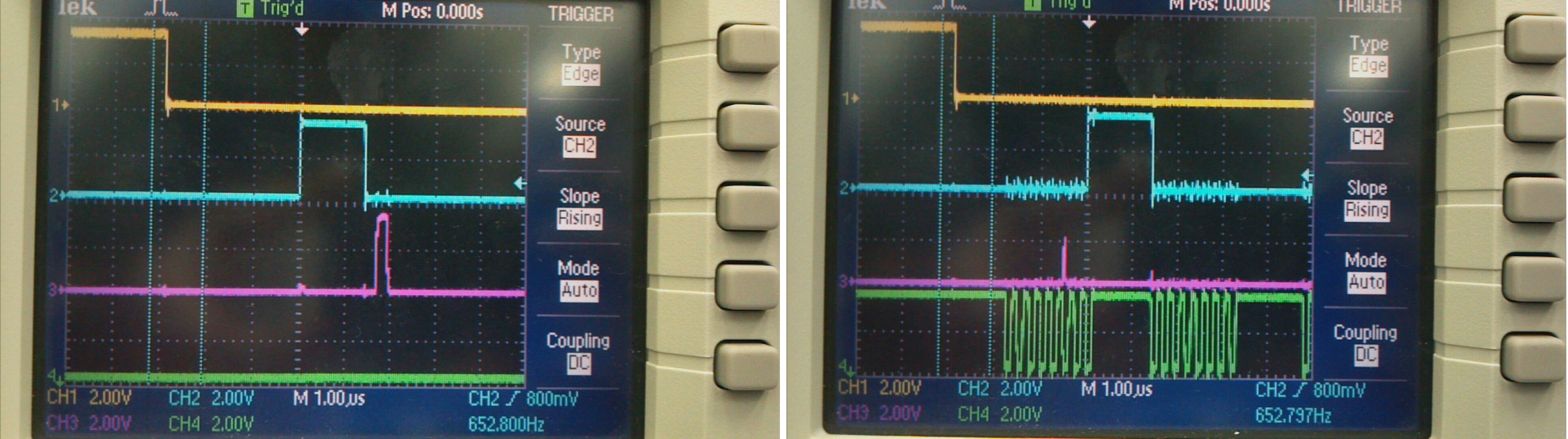
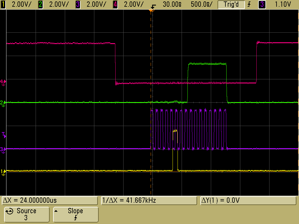
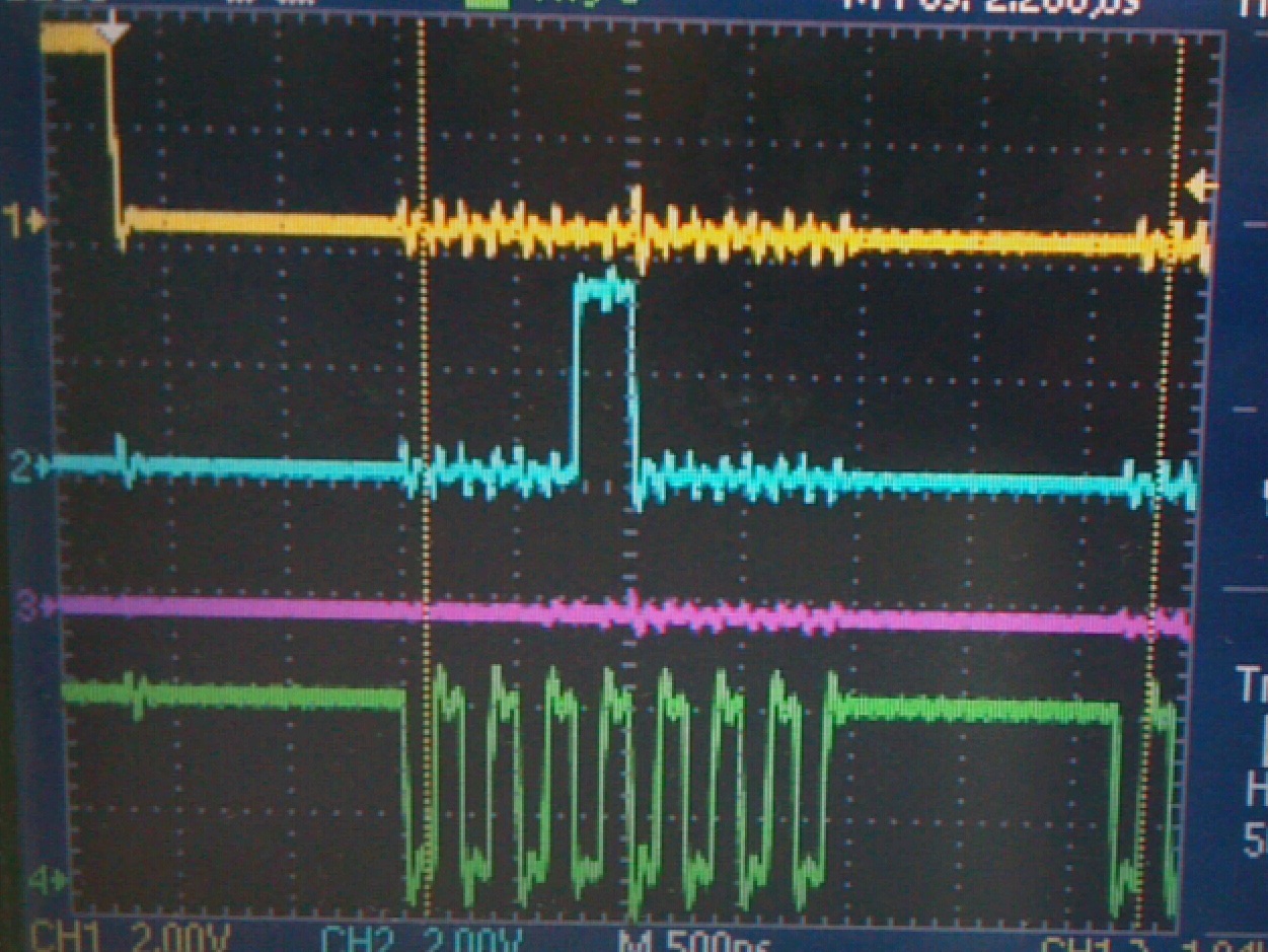
The data looks like it is going out fine, but there is no response from the TDC7200.

The clock signal goes out P2.2(green), MISO/DOUT is on P3.1(pink),  MOSI/DIN is on P3.0(blue), and CS is on P2.2(yellow).

  Any idea what I am doing wrong?

  • Steven,

    Default value of 0x10 register is 0 and may be that's what you are reading. Did you check if you are able to read a 8-bit register correctly? You can try reading byte register 0x01 and you should get 0x40.

    By the way oscillator enable pin must be set high. The device needs a valid clock. Make sure the CLK_SEL jumper is also selected properly.

    You can also take a look at the MSP430 Launch pad code for TDC7200. You can find the code zip under the EVM GUI install folder
    C:\Program Files (x86)\Texas Instruments\TDC1000_7200EVM\Firmware
    There's a basic SPI read/write example project also.

    Thanks,
    Vishy
  • I tried reading register 0x01 and got 0x40 back. I did run into a problem where the signal disappeared if I probed the clock pin. Scope image below.

    I tried to read 0x10 again and saw a return signal, but it disappeared when I changed the code to display the value. I haven't been able to get it back.

  • Hi Vishy,

    I still haven't been able to get a return signal from the TDC register. Any ideas? I'm still getting zeros in response.

    Steven
  • Steven,

    a) Please check ENABLE pin of TDC7200 is set logic high. Otherwise, device is in low power mode and would not respond to SPI access

    b) I have enclosed below a sample SPI read waveform: reading default value (0x0F) of register 0x04

    Please check SPI clock phase/polarity selection in your code.

    Thanks,

    Vishy

  • Vishy, I can read register 0x04 fine. My scope looks about the same as yours. One question: isn't your screen showing 0xFF rather than 0x0F?
  • Yes, default value of 0x04 register is 0xFF. Thanks, Vishy
  • I can successfully read the default values from registers 0x01 and 0x04 (0x40 and 0xFF, respectively), but I have not been able to read anything but the default value (0x00) from the 0x10 register, or any of the other TDC registers.

  • Registers 0x10 onwards are readonly measurement result registers. They will have valid value only when you start a measurement (set START_MEASUREMENT bit in register 0x0) and there's valid start/stop inputs. Please check TDC7200 data sheet.
    Thanks,
    Vishy
  • Ok, now I am writing 0x01 to register 0x00 to set the START_MEASUREMENT bit. I am then reading three bits of data from register 0x10 while sending square wave pulses to the START and STOP channel. The delay is around 30ns, but I am still reading nothing but zeros. Any idea what is wrong?

  • Please review section 8.4.6 of the DS. It has all the steps to go through for a measurement sequence.
    a) Initialize all the registers and then finally set the START_MEAS bit.
    b) Make sure START/STOP are provided after trigger goes high.
    Thanks,
    Vishy
  • I believe I am following the procedure outlined in the data sheet, but what do you mean by "initialize all the registers"?

    I write a 1 to the START_MEAS bit, wait for INTB to go to zero, then read register 0x10h.

    One thing that I have noticed is that I read "FF FF FF" from the TIME1 register if I am not probing the MISO pin, but it drops to "00 00 00" when I connect a probe. Seems to me like the TDC is not driving the MISO pin for some reason.

  • I finally got this to work by abandoning the LaunchPad board and going straight to an FPGA board. I never got a very clean signal from the LaunchPad, so I suspect that the signal was just too noisy.

    I am having some trouble getting the TDC to trigger the pulse generator now. If I understand correctly, the TRIG should go high after a new measurement is started by writing 1 to the Start Measurement bit. As far as I can tell that isn't happening.
  • Steven,
    a) When using TDC7200 booster pack board with launchpad, make sure the GND testpoint close to TP3 is not in contact with Launcpad TXD or RST header. I have noticed sometimes this GND testpoint extends (on the back of the board) long enough to touch the launchapd header pin causing faulty behavior.
    b) Regarding TRIG output, make sure enable pin is high. Check also clock input is there.
    c) You said before it is working with the GUI. Double check it continues work with the GUI with START/STOP test inputs as described in the TDC7200EVM user guide.
    Thanks,
    Vishy