This thread has been locked.

If you have a related question, please click the "Ask a related question" button in the top right corner. The newly created question will be automatically linked to this question.

TDC1000-TDC7200EVM getting various TOF results

Other Parts Discussed in Thread: TDC7200, TDC1000

Hello,

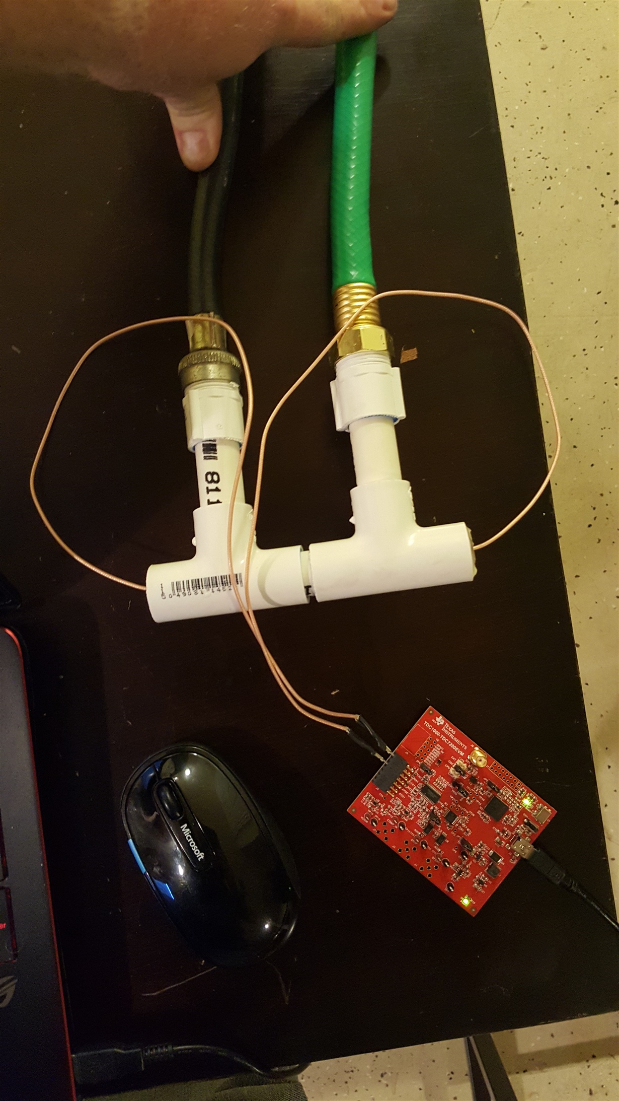
I have gotten an in-line ultra sonic contraption going right now. I have been able to get about 90% accuracy with this test. However, this is not accurate enough for the project I am working on. Even at no flow I am getting about 3 ns TOF when that should be 0 ns. When the flow is running at a constant rate and I run the GUI I am getting about 5 ns deviation in my TOF. Is there something I can do to reduce this deviation in the TOF? I have tried multiple setups for the configuration file and this is about the only one that works for me. Changing any of the averaging values breaks the test and makes the TOF extremely inaccurate ( says 0.3 ns for a 5 gal/min flow rate). Any help would be appreciated! Attached is a photo of the jig I have created and my config file.

Thanks,

Chris

TDC1000_Config0                         45
TDC1000_Config1                         45
TDC1000_Config2                         12
TDC1000_Config3                         03
TDC1000_Config4                         1F
TDC1000_TOF-1                           02
TDC1000_TOF-0                           45
TDC1000_Error_Flags                     00
TDC1000_Timeout                         1B
TDC1000_Clock_Rate                      00
TDC1000_Conts_Trigger                   01
TDC7200_Config1                         02
TDC7200_Config2                         40
TDC7200_Interrupt_Status                07
TDC7200_Interrupt_Mask                  07
TDC7200_Coarse_Cntr_Ov_H                FF
TDC7200_Coarse_Cntr_Ov_L                FF
TDC7200_Clock_Cntr_Ov_H                 FF
TDC7200_Clock_Cntr_Ov_L                 FF
TDC7200_Clock_Cntr_Stop_Mask_H          00
TDC7200_Clock_Cntr_Stop_Mask_L          00
TRIGGER_UPDATE_FREQ                     0000
TDC_AVG/STDEV_NUM_ELEMS                 0002
SAVE_GRAPH_DATA_TO_FILE                 00
FLOW_MODE_SELECT                        01
Y-SCALE_CENTER                          0000
X-SCALE_RANGE                           0032
MEASURE_RTD1                            00
SAVE_RESULT_REGR_TO_FILE                00
GRAPH_MULTI_STOPS                       00
TDC_SELECT                              00
TEMP_RTD_SELECT                         00
TEMP_RTD_MODE                           01
TEMP_AVG/STDEV_NUM_ELEMS                000A
SAVE_TEMP_DATA                          00
GRAPH_YMAX_DATA                         0000000000011170
GRAPH_YMIN_DATA                         FFFFFFFFFFFEEE90
TDC1000-HV_DRV_EN1                      00
TDC1000-HV_DRV_EN2                      00
HV_DRV_EN1_Period                       001E
HV_DRV_EN2_Period                       001E
ENABLE_POWER_CYCLE                      00
CLK_FREQ_(1-16MHz)                      8.000000
CLK_SOURCE_SEL                          00
CPU_CLK_FREQ                            05
CPU_CLK_EN                              00
TDC1000-HV_BST_PWR_EN                   00
HV_BST_PWR_EN_Period                    0000
FWD2REV_FLOW_DELAY                      0000
TDC1000-IMPE_MATCH_EN                   00
ENABLE_UART_STREAM                      00
ENABLE_MSP430TIMER_TDC                  00

  • Chris,
    I will review the config file and let you know. Usually, the two transducers (and any mirrors) alignment is done with CAD tools and precise machining. Otherwise, the echo amplitude seen by each transducer for zero flow could be different resulting in tof differences.
    Thanks,
    Vishy
  • The transducers fit pretty tightly into the 1/2 pvc although there could possibly be a little movement from parallel. What kind of tolerances are there for the alignment 1° or .01°? I have a CAD file and can 3D print but if the pvc isn't straight enough a 3D print job possibly isn't either. Do I have to get this machined?
  • Chris,
    I reviewed the register settings. Please change TDC7200 config2 register value to 0x44 so the number of stops selected is 5 (same as TDC1000). In the graph tab, then you can use "TDC_SELECT" to choose a different STOP or average of the START-STOPxxx to improve accuracy.

    Sorry, we don't have experience in sensor alignment and construction as we used mainly off the shelf sensors.

    Thanks,
    Vishy