This thread has been locked.

If you have a related question, please click the "Ask a related question" button in the top right corner. The newly created question will be automatically linked to this question.

TDC1000 LNA oscillates.

Other Parts Discussed in Thread: TDC1000, MSP430FR5969

Hello everyone,

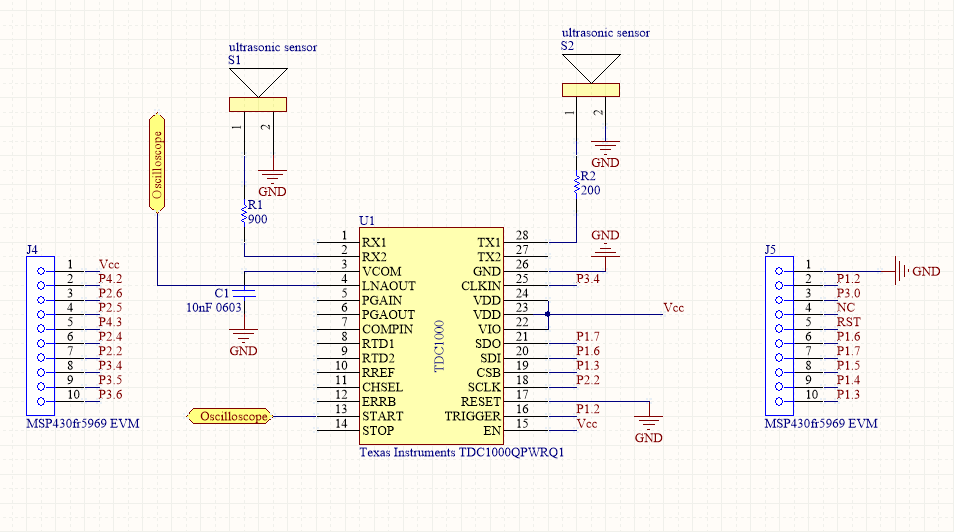
I've been having problems with TDC1000's LNA. I simply wanted test the LNA and connected 900 Ohm resistor, which is connected to RX2, to ground and probed LNAOUT. Results are shown below. The blue trace show LNAOUT pin and the purple trace is the START pin of TDC1000 as it is seen LNAOUT oscillates around roughly VCOM. I use LNA in the resistive mode, mode 0 and everything is default. I also probed VCOM and it looks OK. What might the reason be? By the way I'm not using the EVM I built my own circuit. So far I was able to use TX channels and use SPI to communicate with TDC1000.

  • Please share with us the TDC1000 register settings and also a schematic of your TDC1000 setup. The inputs of the LNA, PGA and comparators should be biased to the VCOM pin's potential. Thanks.
  • Thanks for the answer. I share the circuit I use. I also use MSP430fr5969's launchpad to communicate with TDC1000. I also probed VCOM it looks OK. LNAOUT is probed and it oscillates which is shown in the pictures I shared. I also connected 900 Ohm to ground and it still oscillates. All reigsters are default except CONFIG_0( 0xCD) and TOF_1 (0x14). Btw clock in signal is 5.33 MHz

  • Mode 0 is for use with a single transducer. As an example, you send on transducer connected to TX1 and receive on the same transducer connected to RX2. In Mode 0, TDC1000 defines one channel pair as TX1/RX2.

    In contrast, Mode 1 is for use with 2 transducers. You send on one transducer connected to TX1 and receive on the other transducer connected to RX1. Here, TDC1000 defines one channel pair is TX1/RX1 and the other channel pair as TX2/RX2.

    Hence, if you would like to use 2 transducers then you have to set it up as Mode 1 and the receive should be on RX1. With 5.33MHz clock and 128 divide, looks like you are using a 40kHz transducer. This should fix LNA issue bit if you still see oscillation, try increasing the resistor value or use capacitive mode.

    Thanks,
    Vishy
  • For some reason resistive mode doesn't work for me. It oscillates, I've tried many different values of input resistor, but no hope I suspect it might be related to layout of my circuit(ugly breadboard long wires), but capacitive mode seems to be working right now. I keep experimenting.
  • Here is the thing. I use I use capacitive mode with 5k input resistor and the input signal is shifted to the common omde voltage (external), and also I use 1k resistor to ground at LNAOUT pin in this situation there is no oscillation . When I leave LNAOUT open it saturates even though there is an input signal I see no amplification. When I connect LNAOUT directly to PGAIN pin The circuit amplifies with no problem( PGAOUT is connected to 1k resistor to ground). However, When I connect a low pass filter to PGAOUT(1k and 2.2nF capacitor) it just sits around VCOM and no signal is observed. My question is how should be the interconnections be? Can I just directly connect LNAOUT to PGAIN and PGAOUT to COMPIN (assuming that all signals are biased at VCOM). Is it OK to probe COMPIN pin with passive oscilloscope probe?
  • You can look at the TDC1000-TDC7200EVM board schematic to see the interconnections should be

    www.ti.com/.../sniu021

    Thanks.
  • Hello,

    COMPIN is very sensitive, which is why on the eval board the Test point is not directly on the COMPIN pin but through an op amp.

    Yes, long breadboard wires can cause oscillation in some cases.

    For this part it would be best to experiment with the eval board that is available on the ti.com store.

    Mike