


Hi,
I am planning to design an inductive sensor array, similar as Texas Instruments did with the 16-Button Keypad, (see the documentation TIDU954A) , the following figure is from the mentioned documentation.
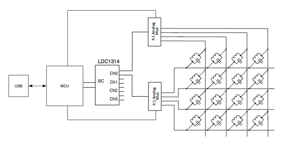
The multiplexed network of this 16 sensors (LC-Tanks) suffers strong crosstalk between sensors, so the application is based on threshold detection but it is not sensing Inductance with a precise resolution.
I am looking for ways to reduce this crosstalk, either take a separate MUX-channel for each sensor (not a network like arrangement, but multiplex multiple MUX) or add a low leakage diode to each LC_tank in this network arrangement. This would clip the oscillation signal as soon it goes below ground.
Here comes my 1. Question: Would the "Resonant Circuit Driver" still be able to excite an LC-Tank at its resonance frequency with a diode in series (clipped V_osc Amplitude)?
The reason why I came to this question is because in all the documentations I studied where V_osc is plotted it appears to be somehow clipped. Maybe the Regulation of I_Drive inside the "Resonant Circuit Driver" leads to an already clipped I_Drive signal. (Nice examples of clipped V_osc in SNOA950 p. 6 or SNAA221A p. 7)
2.Question: Why is V_osc clipped?
I know that the inside of the "Resonant Circuit Driver" is part of IP from Texas Instruments, so I will not ask on further details on that.
But still I would like to have a basic understanding of the signal coming from that "Resonant Circuit Driver" and driving the LC-Tank or whatever I connect to the IN0A and the IN0B pin.
3.Question: Could one assume that the "Resonant Circuit Driver" is approximately an alternating current source with an amplitude that is regulated to a constant level ( I_Drive ) and the frequency of this alternating current is self-adjusting to the resonant frequency of the circuit connected to it (amplitude might be clipped to positive values 2.Question).
Thanks for commenting / replying

