Other Parts Discussed in Thread: LDC1101
Hello!
I'm trying to implement inductive sensor using LDC1000, it is connected to STM32 MCU, gets 8MHz clock from MCO output (3.3v) of MCU and connected to its SPI. I'm using 3.8MHz frequency in LC.
I'm using middle part of LDC1000EVM (with LDC1000 itself), that connected to my own coil by one side, and with short (~5cm) wires to Olimex STM32-H405 board - by other side.
Start sequence:
0x00 -> 0x0B // power down
0x00, 0x3F, 220, (CONFIG_AMP_4_VOLT | CONFIG_RESP_TIME_6144), 0x01, 0xFF, 0xFF, 0x00, 0x00, 0x00, 0x01 -> 0x01..0x0B in one sequence // configure and power up
0x04 -> 0x0A // set INTB to DRDY
After some hard time spent finding errors in datasheet, I can finally program it, can read values, it reacts to metal parts and I can see all this with JScope (J-link tool, that can show graphs based on real-time values from MCU) and in debug window of my IDE.
I have tried to increase polling frequency and met limit at ~1.8kHz, exactly matching formula from datasheet. At 1.9kHz I see approximately each second read from LDC1000 marked ad "Data Not Ready", what is absolutely expected behaviour.
But when I have decreased polling frequency, I met a problem - from time to time I got 0x70 in status register @ 0x20 (instead of 0x30 as usual). Sometimes proximity data also can be read as 0x0000 or as its maximum value. This happens approximately 1-5 times per second, I can not find any correlation with anything.
I tried to use slowest SPI speed, insert delays between changing CS and actual exchange, make polls even less frequently, up to 100Hz, connected 8MHz clock with shortest wire with 22 Ohm resistor in series - and this does not changed anything. Still errors (but between these errors I still can see that LDC1000 is working, proximity data is changing). МСС is 5 volts, VDDIO is 3.3 volts.
Logic analyzer connected to MCU side or LDC1000 side shows me same results - 0x70 from LDC1000 instead of 0x30, so this is not MCU SPI issue.
Can you give me some advice with this problem?
Thank you in advance! :(
p.s. I have tried to solder extra wires to all SPI pads and tried to touch them by hand or place them in different order - and frequency of errors was increased depending on position, from common 1-5 errors per second up to ~50-80. But I cannot understand how this additionally wires can be a reason for LDC1000 "Data Not Ready" bit - I have tried to lower SPI speed by 16 times - and this not changed anything. After I have desoldered that wires, everything was returned to its "stable" state - 1-5 errors per second.
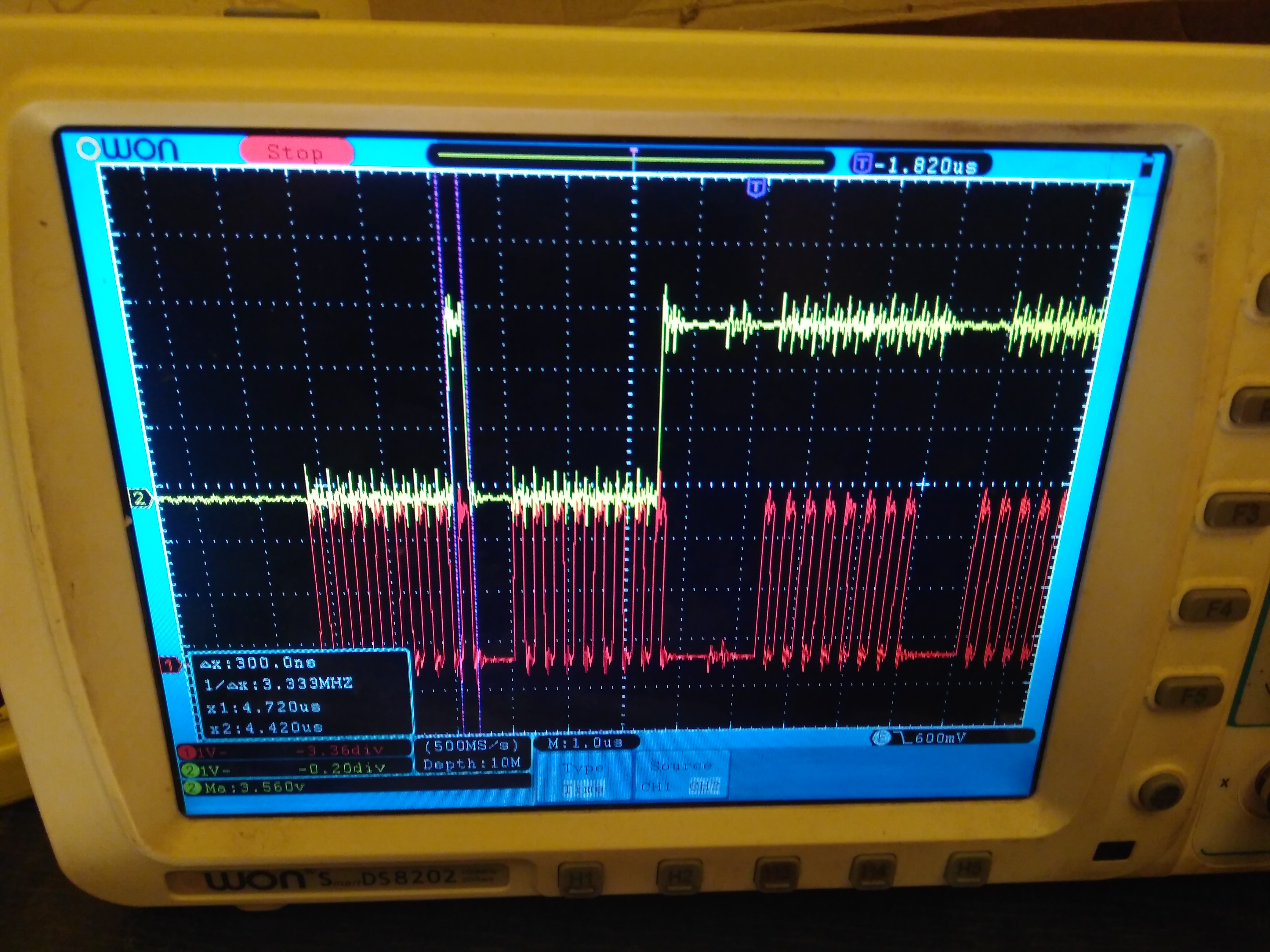
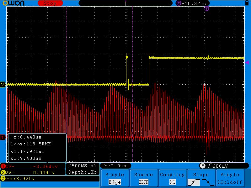
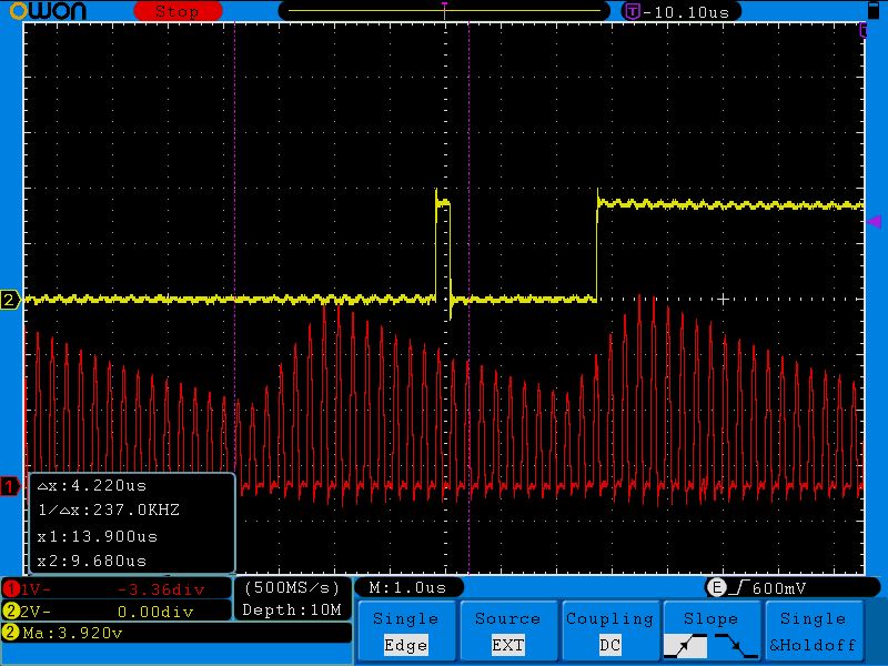
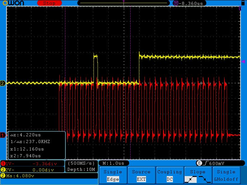
p.p.s. I have tried to turn on DRDY signal on INTB pin and found something strange.. you can see it here:
p.p.p.s. I made test pin to go high when error happened (status byte read as 0x30) and tried to catch this error. Experiments showed that it returns 0x70 instead of 0x30 when DRDY pin pulses high (conversion finished) at the end of first byte of read command (0x20, read from 0x20). I have attached a file when you can see that DRDY pin goes high at end of first command byte just before status byte will be returned. BTW, before this moment 5 DRDY pulses was already (without any read from device), so I caught 6th conversion end here.