This thread has been locked.

If you have a related question, please click the "Ask a related question" button in the top right corner. The newly created question will be automatically linked to this question.

PGA460-Q1: confused with UART communication.

Part Number: PGA460-Q1
Other Parts Discussed in Thread: PGA460, ENERGIA, BOOSTXL-PGA460, LMP91000, SN65HVDA100-Q1

hello team,

i came across pga460-q1 it well suits for my distance sensing application. i had some confusion about UART communication. i would like to interface pga460 with arduino uno. can anyone help me out with this. and am confused with eeprom write and burn methods. please help me with this. and please suggest me exact coding procedure for both pga460 and arduino.

advance thanks...  

  • Hi Pradeep,
    Have you referred to the PGA460-Q1 Software Development Guide (www.ti.com/.../slaa730) and PGA460 Energia Library and Code Example (www.ti.com/.../slac741)

    In these documents, we provide example code, and demonstrate how to structure the UART master transmit data in the library files.

    The EEPROM burn function is also provided as an example. Here is the code snippet:

    ///*** EEPROM Program Burn - BEGIN***///
    byte pga460::burnEEPROM()
    {
    byte burnStat = 0;
    byte temp = 0;

    // Write "0xD" to EE_UNLCK to unlock EEPROM, and '0' to EEPRGM bit at EE_CNTRL register
    regAddr = 0x40;
    regData = 0x68;
    byte buf10[5] = {syncByte, SRW, regAddr, regData, calcChecksum(SRW)};
    Serial1.write(buf10, sizeof(buf10));
    delay(1);

    // Write "0xD" to EE_UNLCK to unlock EEPROM, and '1' to EEPRGM bit at EE_CNTRL register
    regAddr = 0x40;
    regData = 0x69;
    buf10[2] = regAddr;
    buf10[3] = regData;
    buf10[4] = calcChecksum(SRW);
    Serial1.write(buf10, sizeof(buf10));
    delay(1000);

    // Read back EEPROM program status
    pga460SerialFlush();
    regAddr = 0x40; // start of EDD
    byte buf9[4] = {syncByte, SRR, regAddr, calcChecksum(SRR)};
    Serial1.write(buf9, sizeof(buf9));
    delay(10);
    for(int n=0; n<3; n++)
    {
    if(n==1)
    {
    burnStat = Serial1.read();
    }
    else
    {
    temp = Serial1.read();
    }
    }

    return burnStat;
    }
    ///*** EEPROM Program Burn - END***///
  • thank you Akeem Whitehead....

    so after unlocking the eeprom can we write all eeprom registers..

    if not tell me the steps..

    thank u... 

  • Hi Pradeep,

    You'll only want to unlock the EEPROM to save the current values of the shadow registers. Typically, you'll want to edit the shadow registers (volatile memory) during experimentation. You do not have to unlock or burn the EEPROM to modify the shadow registers.

    Here is a note from the PGA460-Q1 Users' Guide:

    3.5.1.6.1 Programming EEPROM
    All of the write commands executed by the GUI write to shadow registers, not directly to the EEPROM.
    The shadow registers are referenced for all operations of the device. At start-up, the PGA460-Q1 device
    loads the shadow registers with the values stored in the EEPROM. If the PGA460-Q1 device is power
    cycled, the shadow registers are cleared and the shadow registers are reloaded with the EEPROM-based
    values.

    To save the present values in the shadow registers to the EEPROM, click the Program EEPROM button to
    burn the values to the EEPROM. After the shadow registers have been burned to the EEPROM, the
    device keeps the most recently updated values prior to the power cycle.

    To reload the EEPROM-based values to the shadow registers, click the Reload EEPROM button.
    The threshold values are stored in RAM and cannot be burned to memory. The threshold values must be
    written to after every instance of the PGA460-Q1 power-cycle and start-up.
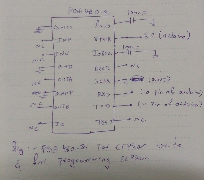
  • hello Akeem Whitehead. this what my algorithm and circuit is.
    tx of pga to 10 pin of arduino.
    rx of pga to 11 pin of arduino.
    Firstly am writing eeprom with bulk command
    And them am programming with unlock and programming command
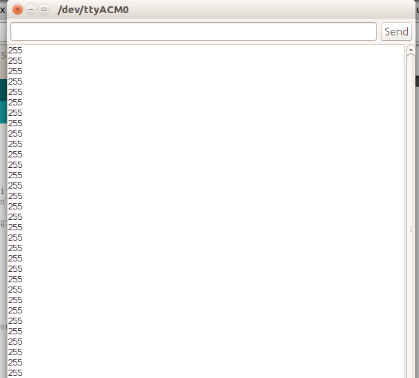
    Finally am reading the eeprom values, but its only giving bunch of 255 values. I think bulk write and programming is not working properly in my algorithm.
    Can you please help me with this problem what am facing...


    #include <SoftwareSerial.h>

    SoftwareSerial mySerial(10,11);

    #define syncByte 0x55
    byte EEBW = 0x60;//eeprom bulk write
    byte EE_UNLCK = 0x50;// eeprom unlock
    byte EEREAD = 0x48;// eeprom read
    byte USER_DATA[20];
    byte burnStat = 0;
    byte temp = 0;

    void setup()
    {
    pinMode(10, INPUT);
    pinMode(11, OUTPUT);
    mySerial.begin(9600);//pga comm
    Serial.begin(9600);//serial monitor print


    eeprom_bulkwrite();
    eeprom_unlock_prgrm();
    eeprom_read();

    }
    void loop()
    {
    }


    void eeprom_bulkwrite()

    {

    for (int i=0;i<20;i++)
    {
    USER_DATA[i]= 0x11;
    }
    byte TVGAIN0 = 0xAA;
    byte TVGAIN1 = 0xAA;
    byte TVGAIN2 = 0xAA;
    byte TVGAIN3 = 0x51;

    byte TVGAIN4 = 0x45;
    byte TVGAIN5 = 0x14;
    byte TVGAIN6 = 0x50;
    byte INIT_GAIN = 0x54;
    byte FREQUENCY = 0x32;
    byte DEADTIME = 0xA0;
    byte PULSE_P1 = 0x08;
    byte PULSE_P2 = 0x10;
    byte CURR_LIM_P1 = 0x55;
    byte CURR_LIM_P2 = 0x55;
    byte REC_LENGTH = 0x19;
    byte FREQ_DIAG = 0x33;
    byte SAT_FDIAG_TH = 0xEE;
    byte FVOLT_DEC = 0x7C;
    byte DECPL_TEMP = 0x4F;
    byte DSP_SCALE = 0x00;
    byte TEMP_TRIM = 0x00;
    byte P1_GAIN_CTRL = 0x09;
    byte P2_GAIN_CTRL = 0x09;

    byte buf1[46] = {syncByte, EEBW, USER_DATA[0], USER_DATA[1], USER_DATA[2], USER_DATA[3], USER_DATA[4],
    USER_DATA[5], USER_DATA[6], USER_DATA[7], USER_DATA[8], USER_DATA[9],
    USER_DATA[10], USER_DATA[11], USER_DATA[12], USER_DATA[13], USER_DATA[14],
    USER_DATA[15], USER_DATA[16], USER_DATA[17], USER_DATA[18], USER_DATA[19],
    TVGAIN0,TVGAIN1,TVGAIN2,TVGAIN3,TVGAIN4,TVGAIN5,TVGAIN6,
    INIT_GAIN,FREQUENCY,DEADTIME,
    PULSE_P1,PULSE_P2,CURR_LIM_P1,CURR_LIM_P2,
    REC_LENGTH,FREQ_DIAG,SAT_FDIAG_TH,FVOLT_DEC,DECPL_TEMP,
    DSP_SCALE,TEMP_TRIM,P1_GAIN_CTRL,P2_GAIN_CTRL};


    mySerial.write(buf1, sizeof(buf1));
    delay(50);
    }

    void eeprom_unlock_prgrm()
    {
    byte regAddr = 0x40;
    // Write "0xD" to EE_UNLCK to unlock EEPROM

    byte regData = 0x68;
    byte buf2[4] = {syncByte, EE_UNLCK, regAddr, regData};
    mySerial.write(buf2, sizeof(buf2));

    delay(1);

    // Write '1' to EEPRGM bit at EE_CNTRL register

    byte regData1 = 0x69;
    byte buf3[4] = {syncByte, EE_UNLCK, regAddr, regData1};

    mySerial.write(buf3, sizeof(buf3));

    delay(1000);
    }

    void eeprom_read()
    {
    //Read back EEPROM program status
    //pga460SerialFlush();
    byte regAddr = 0x40; //start of EDD
    byte buf4[3] = {syncByte, EEREAD, regAddr};
    mySerial.write(buf4, sizeof(buf4));
    delay(10);
    for(int n=0; n<44; n++)
    {
    if(n==1)
    {
    burnStat = mySerial.read();
    Serial.println(burnStat);
    }
    else
    {
    temp = mySerial.read();
    Serial.println(temp);
    }
    }
    }

    And what am getting after reading from eeprom

  • Hi Pradeep,

    How are you powering the PGA460-Q1? The minimum supply voltage requirement is 6V. If you are using the Arudino's 5V rail to power the PGA460-Q1, our device will not function or work properly.

    Are you able to read any data successfully from the PGA460-Q1?

    Is the Arduino 3.3V or 5V logic level referenced? If the logic level is 3.3V, the PGA460-Q1's TXD and RXD pins are set to 3.3V by default, and should be working properly. If the logic level must be 5V, then:

    The digital voltage-level selection performed by the TEST pin is executed at device power up. On power-up, the
    device checks the level of the TEST pin. If the level is low, the digital output pins operate at 3.3 V. If the TEST
    pin is tied high (3.3 V or 5 V are both considered high state), the digital output pins operate at a 5 V. This
    condition is latched in the PGA460-Q1 device so that the test mux can further use the TEST pin as previously
    described. If the application requires that a 5-V digital output is used and a test mux output must be extracted
    from the PGA460-Q1 device, then a weak pullup resistor on the TEST pin can be connected as shown in
    Figure 40 (of the datasheet).

  • Hello,
    The we are using PGA460-Q1 in our design. The EVM schematics shows external SRAM 23LC512. is it required to include 23LC512 also? else the internal EEPROM is sufficient for the data capture.
    Regards,
    Sumathi
  • Hello, Can we connect 12V to PGA, VVPWR_XF input and centertap of transformer?

    Regards,
    Sumathi
  • Hi
    I think Internal EEPROM is enough.
    Are you using BOOSTXL-PGA460 or only a PGA460 chip.

  • Hello Pradeep,
    Thanks for the reply.
    We are using only the PGA460-Q1 related circuit with transformer. The IO, and UART TX and RX is interfaced to a ARM based micro-controller.
    Since the min voltage input for PGA460 is 6V, we have connected 12V. The query is do we require any level translator for UART TX, RX ..since the microcontroller is 3.3V logic?

    Kindly reply,

    Regards,
    Sumathi
  • Hi sumathi
    I had same confusion, but now i overcome from that problem.
    Just read "Apr 12, 2017 10:42 PM" post. Akeem replied perfectly.
  • Hey Pradeep,
    Thanks so much for the quick reply.
    i really appreciate for the clarifications.
    I have one more query, but this is regarding the CO2 sensor. can wee use LMP91000 with MG812 for CO2 gas sensor applications. the pin connection of MG812 to LMP91000, RE, CE and WE not sure. we are connecting the heater pin of MG812 to 5V. The other two pins to (RE &CE shorted) and WE. Will this work?
  • Hello, Can we connect 12V to PGA, VVPWR_XF input and centertap of transformer?

    Regards,
    Sumathi
  • hello sumathi
    Well i don't much about CO2 sensors.

    Can we connect 12V to PGA, VVPWR_XF input and centertap of transformer?
    you can give upto 28v DC to PGA. But i don't really know how much maximum voltage i can give to transformer. I had chosen 3.3v for transformer.
  • Sumathi,
    Yes, you can connect 12V to both the PGA460's VPWR pin and the center-tap of the transformer. You can control the peak-to-peak voltage at the secondary of the transformer (which connects to the transducer) by adjusting the PGA460's preset driver current limit (between 50m-500mA). Adjusting the driver current limit effectively changes the equivalent turns ratio of the transformer, so that you do not overdrive the transducer with a large center-tap voltage (such as 12V).
  • EEPROM Requirements:
    The PGA460 does not require any external EEPROM memory, and can be operated using only UART or TCI. The BOOSTXL-PGA460 EVM only includes the external EEPROM for the specialized test use-case of capturing the synchronous mode output data, which is not a standard feature. The PGA460's internal EEPROM and RAM are able to store all the necessary configuration and result information, which the external microcontroller can read directly via UART (TXD and RXD only; SCLK can be pulled to ground via a 10kOhm resistor if not used) or TCI.

    UART Logic Level:
    When using UART, the PGA460 is able to internally generate the 3.3V or 5.0V logic rails depending on the start up condition of the TEST pin. If TEST is left floating or pulled to ground via 10kOhm resistor, then the logic level will be set to 3.3V. If TEST is pulled high via a 100kOhm resistor to 5V, then the logic level will be set to 5V. The RXD, TXD, SCLK, DECPL, and TEST pins are affected by this selection.
    See PGA460 datasheet section 7.3.12 TEST Pin Functionality for details. No level translator is required for the UART pins.

    IO Logic Level:
    The IO pin is referenced to VPWR (6-28V). To interface this to a low-voltage logic level micro, a level-translator/transceiver is required. For TCI or low-speed One-Wire-UART (<19.2kBaud), the SN65HVDA100-Q1 can be used. For high-speed One-Wire-UART, the discrete OWU implementation on the BOOSTXL-PGA560 circuit can support these communication speeds.

    Note:
    You do not need to use both UART (TXD/RXD) and TCI (IO). Only one of these communication interfaces is required.