This thread has been locked.

If you have a related question, please click the "Ask a related question" button in the top right corner. The newly created question will be automatically linked to this question.

LM35: reading negative temperatures with confugiuration from figure 18

Part Number: LM35

Hi,

I'm trying to make a temperature sensor with negative readings...

I want to know  what is the Vout in figure 18 from datasheet, is a configuration with single supply...

In the datasheet we have no information about Vout in this configuration...

But we have information about Vout in dual supply configuration (next picture)

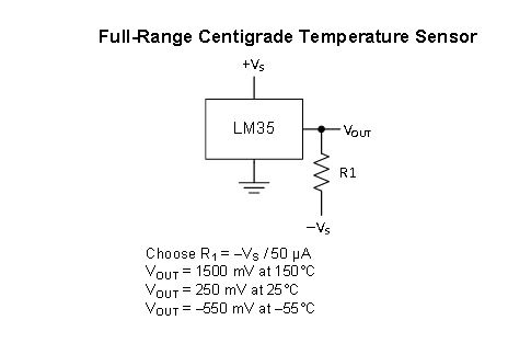
I've no lab to test negative temperatures, so I really need this information..

best regards

  • Magno,

    Can you please provide the full orderable part number you are using?  There are multiple versions of this device and different owning product groups.  This will help us move to correct forum for support.

    Regards,

    Wade

  • sorry, But how can I get it?
    :S
    In my sensor is stamped LM35OZ...
  • Hi,

    sorry but how can I get it?

    in the device that I'm using is stamped LM35OZ...
  • I suspect that is a DZ vs OZ.
    That is enough information. I will move this to the sensing forum.
    Regards,
    Wade
  • These are typical diodes which have a 0.7V forward voltage. They are lifting the GND pin of the LM35 about 1.4V above system ground. This offset combined with the 18kohm connected to actual system ground allows the device to drive to a voltage below 0V. The output characteristic is still the same as described in Section 7.3 page 13.

    Ren
  • Hi Magno,

    From figure 18 we see that

    Vout ("+" node relative to supply GND) = 2*Vd+10mV/oC,

    where Vd = forward voltage of the 1N914 diode, which depends on the diode forward current (should be close to the quiescent current of LM35)

    The diodes are used to create a 2*Vd reference for the LM35 so that there will be headroom for LM35 to measure negative temperatures.

    Note that the differential output (See the "+" and "-" nodes in figure 18) is still Vout = 10mV/oC.

    Example calculations:

    Let's assume Vd=0.6 V for figure 18 and the operating temperature is -55oC to 150oC.

    Vout ("+" node relative to supply GND) ranges from 0.65V to 2.7V.

    @-55: -55oC.*10mV/oC+2*0.6V = 0.65V

    @150: 150oC.*10mV/oC+2*0.6V = 2.7V

    ADC considerations:

    Single-ended ADC

    As you can see, for single-ended measurement the output accuracy depends on the reference voltage provided by the diode stack.  The user will need to monitor both the LM35 and diode reference voltage in order to have reasonable accuracy over temperature.

    Differential ADC

    The Vout ("+" and "-" nodes) is independent of Vd.  However, you still need a stable common mode reference 

    The bottom line is your system accuracy can't be higher than your reference voltage.

    -Kelvin

  • Hi Kelvin,

    many thanks for your answer...

    but I can't understand this expression...


    @-55: -55ºC.*10mV/ºC+2*0.6 = 0.65V

    did you mean

    -55*0.010 + 2*0.6 ??

    best regards,
    Magno
  • I'm glad I could help.  You're correct. 10mV = 0.010V.  I forgot to add the unit next to 0.6, which should've been 0.6V.

  • Many Thanks Kelvin,

    I will try this configuration for my project...

    best regards,

    Magno Campos