Other Parts Discussed in Thread: MSP430FR5969
Hello,
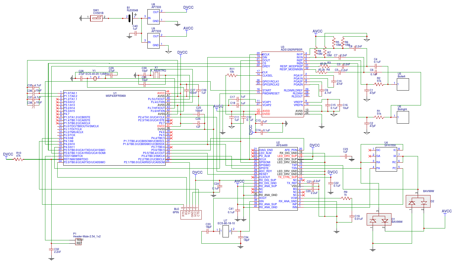
I have built up a circuit of MSP430FR5969 controlling AFE4400 to get PPG signal which works fine but it does not work when I transfer all the circuit into a PCB version and I used the same code. I have checked the voltages of severals pins and the result seems very strange to me. The voltage of pin TXP is 0.9V which is significant lower than the value 1.63V in my bread board version. However, I also compared the voltage of TXN which is 1.48V in PCB version and 1.84V in bread board version and the voltages in TX_REF, BG and VCM are exactly the same to the each other with value of 0.44V, 0.96V,0.9V, respectively. I really cannot figure out why only the voltage in TXP is quite low while others are pretty the same?
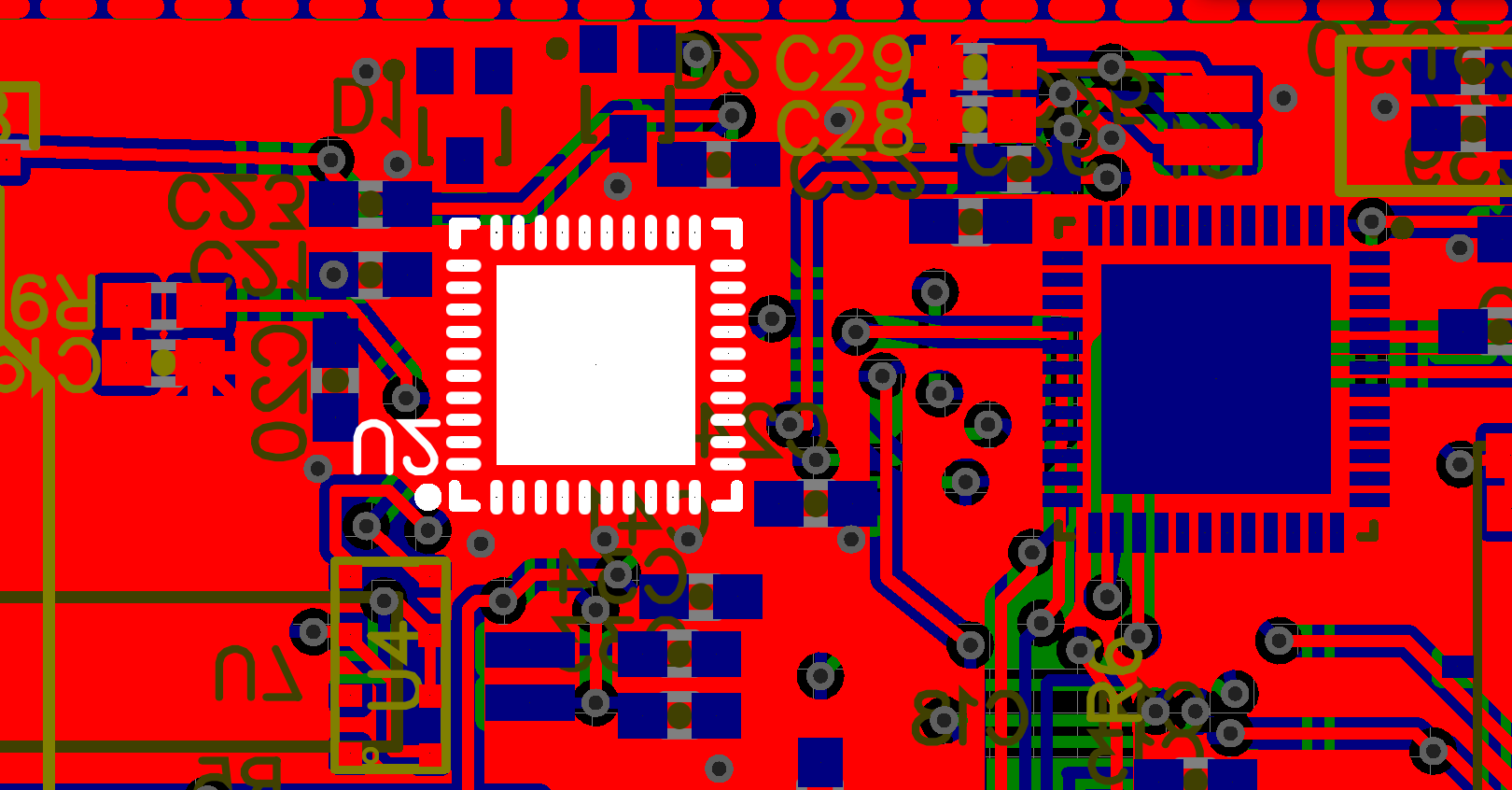
I'm also attaching my schematic, PCB layout (the highlighted U2 is the footprint of AFE4400) and the code here. I really appreciate if you could find the problem for me.
void setup_AFE4400 ()
{
AFE4400Write(CONTROL0,0x000008); //reset
// Serial.println("AFE4400 Initialization Starts");
AFE4400Write(CONTROL0,0x000000);
AFE4400Write(TIAGAIN,0x000000); // CF = 5pF, RF = 500kR
AFE4400Write(TIA_AMB_GAIN,0x000005); // Timers ON, average 3 samples
AFE4400Write(LEDCNTRL,0x012020);
// AFE4400Write(LEDCNTRL,0x010404);
AFE4400Write(CONTROL2,0x020100); // LED_RANGE=100mA, LED=50mA
AFE4400Write(CONTROL1,0x000102); // Timers ON, average 3 samples
AFE4400Write(PRPCOUNT, 0X001F3F);
AFE4400Write(LED2STC, 0X0017A2); //timer control
AFE4400Write(LED2ENDC,0X001F3E); //timer control
AFE4400Write(LED2LEDSTC,0X001770); //timer control
AFE4400Write(LED2LEDENDC,0X001F3F); //timer control
AFE4400Write(ALED2STC, 0X000032); //timer control
AFE4400Write(ALED2ENDC, 0X0007CE); //timer control
AFE4400Write(LED2CONVST,0X000004); //timer control
AFE4400Write(LED2CONVEND, 0X0007CF); //timer control
AFE4400Write(ALED2CONVST, 0X0007D4); //timer control
AFE4400Write(ALED2CONVEND,0X000F9F); //timer control
AFE4400Write(LED1STC, 0X000802); //timer control
AFE4400Write(LED1ENDC, 0X000F9E); //timer control
AFE4400Write(LED1LEDSTC, 0X0007D0); //timer control
AFE4400Write(LED1LEDENDC, 0X000F9F); //timer control
AFE4400Write(ALED1STC, 0X000FD2); //timer control
AFE4400Write(ALED1ENDC, 0X00176E); //timer control
AFE4400Write(LED1CONVST, 0X000FA4); //timer control
AFE4400Write(LED1CONVEND, 0X00176F); //timer control
AFE4400Write(ALED1CONVST, 0X001774); //timer control
AFE4400Write(ALED1CONVEND, 0X001F3F); //timer control
AFE4400Write(ADCRSTCNT0, 0X000000); //timer control
AFE4400Write(ADCRSTENDCT0,0X000003); //timer control
AFE4400Write(ADCRSTCNT1, 0X0007D0); //timer control
AFE4400Write(ADCRSTENDCT1, 0X0007D3); //timer control
AFE4400Write(ADCRSTCNT2, 0X000FA0); //timer control
AFE4400Write(ADCRSTENDCT2, 0X000FA3); //timer control
AFE4400Write(ADCRSTCNT3, 0X001770); //timer control
AFE4400Write(ADCRSTENDCT3, 0X001773);
AFE4400Write(CONTROL0,0x000001);
delay(1000);
}
Thanks,
Yiwen