This thread has been locked.

If you have a related question, please click the "Ask a related question" button in the top right corner. The newly created question will be automatically linked to this question.

IWR1443: Running Continuous Wave Mode on IWR1443 for Testing Purposes

Part Number: IWR1443

Hi,

I want to run continuous wave mode on the chip for test purpose. For example, let the IWR1443 output 77GHz signal continuously and test the RF signal.
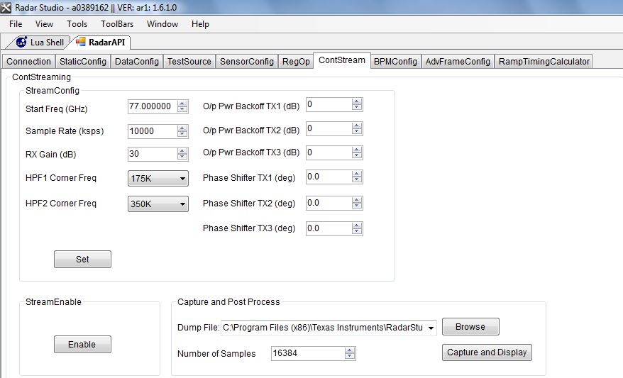
I found a tab in radar studio named ContStream. Can this be used for this purpose?

Thanks,

Chris

  • The Continuous Streaming tab can be used for RF measurements. This tab contains the
    configurations of the data path to transfer the captured ADC samples continuously without
    missing any sample to an external host.
    1. Set the StreamConfig parameters.
    2. Enable Continuous Streaming
    3. Select Capture and Display

    Start Freq - this is the starting RF frequency for the chirp
    SampleRate - This is the DFE (decimated 1x complex output) 11200 - 11.2Msps, with 80%BW(1-10Mhz Beat freq)
    Rx Gain(db) - you would run several experiments where you have uncompressed signals, you would increase the gain, until you see clipping, then back off by 3 to 6db.
    HPF1 Corner Freq, HPF2 Corner Freq - this provides a High Pass filter to desensitize close in objects (provides Low frequency attenuation)
    O/P Pwr Backoff - value below 12db for max of 2 Tx1,2,3 outputs
    Phase Shifter Tx1,2,3 please leave these at 0 for now.
    Set the Chirp Rx parameters
    Set the Dump file, and num samples on PC
    Enable the Streaming
  • As under the tab, there is no chip slope configure, the output of the RF signal is fixed with the start frequency, right?
  • Yes I don't see the bandwidth control, there must either be another setting, or a default value.