This thread has been locked.

If you have a related question, please click the "Ask a related question" button in the top right corner. The newly created question will be automatically linked to this question.

DRV5053: DRV5053ca

Part Number: DRV5053
Other Parts Discussed in Thread: DRV425

Hi TI,

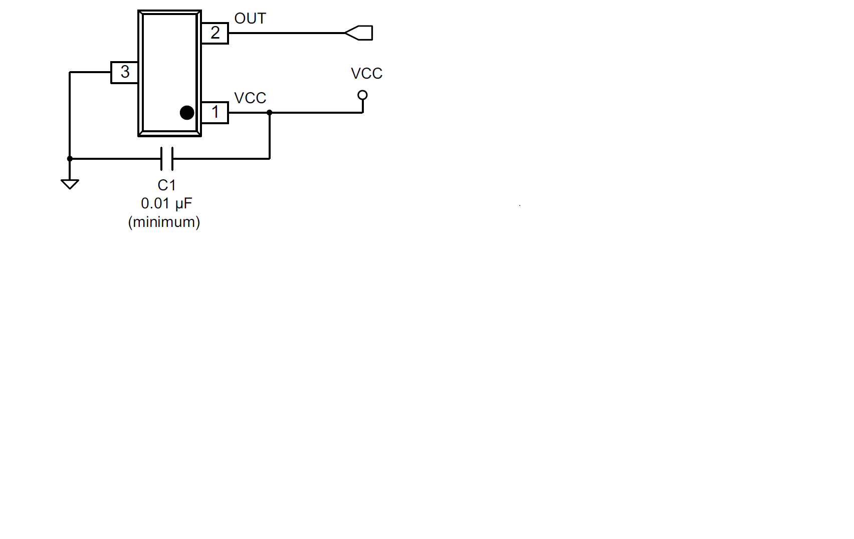
I'm using DRV5053 hall effect sensor  to measure the AC current flowing through a wire which is of nearly 6A,

But my problem here is as mentioned in Datasheet if DRV5053 im not getiing  ac voltage as output im getiing DC voltage as my output for basic  connection please find the  attachment for the circuit.

  • Hi Mohan,

    The DRV5053 is a linear device and you should be seeing an AC output signal if you're exciting the DRV with an AC magnetic field. There could be multiple reasons why this may not be happening. A few questions:

    1) Is the output voltage around 1V? This would mean the DRV is sensing a flux density of close to 0T. Try moving the sensor closer to the wire, increasing the current magnitude (you can try this with a DC current signal first) or increasing the number of turns in the wire, to see if the output starts fluctuating.

    2) Is the output voltage close to 0V or 2V? This would mean that the DRV is being saturated by a field that is too strong. Try moving the DRV away from the conductor, or reducing the current value. Just out of curiosity, does your current signal have a DC offset of 6A with a smalll AC signal super-imposed on it, or does it actually vary between 0A and 6A?

    3) What is the supply current of the DRV when there is no current flowing through the conductor you are monitoring? The typical quiescent current should be about 2.7mA. If you're having power-up issues or if the device is defective or if the device output is shorted to GND on the PCB then you should see an abnormal value (very high or low compared to 2.7mA).

    Best Regards,
    Harsha

  • Hi Harsha,
    Please find the below answers for your questions

    1) Is the output voltage around 1V? This would mean the DRV is sensing a flux density of close to 0T. Try moving the sensor closer to the wire, increasing the current magnitude (you can try this with a DC current signal first) or increasing the number of turns in the wire, to see if the output starts fluctuating.

    >>Yes i'm getting output voltage of 1v(DC voltage) when no current in the wire,when i switch on the motor the wire was carrying 4A of Ac current
    But even in that condition i'm getting 1V(DC voltage) output.

    One more thing I'm Getting output increasing from 1v to 1.96v of Dc voltage from DRV when it is intract with pure magnet,but when i try to measure Ac current flowing through the wire i'm getting constant output of 1V DC voltage.

    2) Is the output voltage close to 0V or 2V? This would mean that the DRV is being saturated by a field that is too strong. Try moving the DRV away from the conductor, or reducing the current value. Just out of curiosity, does your current signal have a DC offset of 6A with a smalll AC signal super-imposed on it, or does it actually vary between 0A and 6A?

    >> I'm using Hall sensor to measure the AC current flowing through a motor ,when i measure through clamp meter motor is taking 3.2A of current.

    3) What is the supply current of the DRV when there is no current flowing through the conductor you are monitoring? The typical quiescent current should be about 2.7mA. If you're having power-up issues or if the device is defective or if the device output is shorted to GND on the PCB then you should see an abnormal value (very high or low compared to 2.7mA).

    >> supply was given by 5V ,2A power supply so there will be no issue in the power part.


    Please provide some solution to measure the AC current flowing through the wire,as shown in blow link should i use flux concentrator to measure the Flux flowing through the wire ??
    LINK:www.ti.com/.../tidu522a.pdf
  • Hi Mohan,

    Yes, using a flux concentrator as shown in the reference design you've been looking at is the easiest way to gain up the magnetic flux signal to the DRV5053. Flux concentrators, like permanent magnets, are made of magnetic materials that are better able to concentrate magnetic field lines compared to air.

    As an alternate idea have you considered using one of our fluxgate magnetic sensors such as the DRV425, which are particularly well-suited to current measurement? The DRV425 has an input range that is 10x smaller than the DRV5053 (VA version has narrowest input range of +/-22mT). This means that the DRV425 is able to measure much smaller fields than the 5053 without requiring an external flux concentrator. It also has a 20kHz bandwidth which should be more than sufficient to support your application. We are also currently working on a reference design for using the DRV425 to measure small AC currents, which would be useful to you. If you are interested, I can connect you with the Applications engineer who supports our fluxgate sensors.

    Best Regards,
    Harsha

  • Hi Harsha,

    Thank you very much for the reply,

    Please connect us with your  Application engineer as early as possible because this project is very much important to us.

    Below is my contact details fell free to contact any time.

    Contact num: 9035450303,7204021382

    Email:  mohan@vinfinet.com

  • Hi Mohan,

    The DRV425 could be used to measure a current on a trace on a PCB but you will have a few design considerations.  Because the sensitivity is much higher for the DRV425 (saturates at 2mT) you will also need to take into account unwanted magnetic fields.  You will need to determine if you will need to either shield unwanted magnetic fields or not.  The unwanted fields can be caused by the return currents, other currents on the board, or earth's magnetic field. 

    There are 4 methods we have used that can be used individually or together to eliminate external sources:

    1. Placing a magnetic material surrounding the sensor and current to be measured.  This shields the unwanted fields form the sensor.
    2. Place two DRV425 in a manner to cancel out the common field that comes from an outside source, there is an example of this in our Bus Bar Theory of Operation
    3. Filter out unwanted frequencies.  For example if you are measuring 60Hz you can filter out earth's magnetics field which would be a DC signal.  This would not filter out neighbor currents.
    4. Calibrate influence from external fields.  For return currents this is normally a change in the gain from ideal.

    What accuracy are you trying to meet?  Can you calibrate?  These values will help determine what is required. 

    I can share some simulations from FEMM which is a free software to simulate magnetic fields in 2D and calculate what is expected.

  • Hi Javier Contrera,

    Thank you for your reply,please provide the simulation data which can be helpful for our design.

  • Hi Harsha,

    DRV425 is SMD package can you please suggest me any sensor with both through hole and smd because it will be helpful for our R&D
  • Hi Javier Contrera
    DRV425 is SMD package can you please suggest me any sensor with both through hole and smd because it will be helpful for our R&D
  • Mohan,

    I have attached my 2d FEM simulation file.  I placed a drawing below with the dimensions is mil.  The simulation is ran with 10A on the copper interlayers.  The magnetic field seen at each DRV425 is about 1.06mT.  The math applied to the circuit is similar to that of the bus bar regarding stray fields.  You can see them in section 4.1 in the Bus Bar Theory of Operations

    Notice each DRV425 is facing in opposite directions below.  The is because the field is circular so both will read the same polarity from the current being measured.  Any stray fields will measure in opposite directions.  You can add a circuit just like the circuit in the bus bar application or measure the output separately and apply the math in post processing.  I have attached the FEM simulation as well.

    Please let me know if you need further assistance.https://e2e.ti.com/cfs-file/__key/communityserver-discussions-components-files/1023/OvertheTrace_5F00_e2e.FEM