This thread has been locked.

If you have a related question, please click the "Ask a related question" button in the top right corner. The newly created question will be automatically linked to this question.

TDC1000-TDC7200EVM: E315391 SV601098001A

Part Number: TDC1000-TDC7200EVM


hi I bought the TDC1000-TDC7200EVM

and I made experiment with the sensor that T.I supplied

it is our first step to work with the T.I product

TDC1000_Config0                         41
TDC1000_Config1                         41
TDC1000_Config2                         00
TDC1000_Config3                         04
TDC1000_Config4                         5F
TDC1000_TOF-1                           03
TDC1000_TOF-0                           FF
TDC1000_Error_Flags                     00
TDC1000_Timeout                         63
TDC1000_Clock_Rate                      00
TDC1000_Conts_Trigger                   01
TDC7200_Config1                         02
TDC7200_Config2                         40
TDC7200_Interrupt_Status                07
TDC7200_Interrupt_Mask                  07
TDC7200_Coarse_Cntr_Ov_H                FF
TDC7200_Coarse_Cntr_Ov_L                FF
TDC7200_Clock_Cntr_Ov_H                 FF
TDC7200_Clock_Cntr_Ov_L                 FF
TDC7200_Clock_Cntr_Stop_Mask_H          00
TDC7200_Clock_Cntr_Stop_Mask_L          00
TRIGGER_UPDATE_FREQ                     0000
TDC_AVG/STDEV_NUM_ELEMS                 0032
SAVE_GRAPH_DATA_TO_FILE                 00
FLOW_MODE_SELECT                        00
Y-SCALE_CENTER                          0032
X-SCALE_RANGE                           0032
MEASURE_RTD1                            00
SAVE_RESULT_REGR_TO_FILE                00
GRAPH_MULTI_STOPS                       00
TDC_SELECT                              00
TEMP_RTD_SELECT                         00
TEMP_RTD_MODE                           01
TEMP_AVG/STDEV_NUM_ELEMS                000A
SAVE_TEMP_DATA                          00
GRAPH_YMAX_DATA                         0000000000004870
GRAPH_YMIN_DATA                         000000000000480C
TDC1000-HV_DRV_EN1                      00
TDC1000-HV_DRV_EN2                      00
HV_DRV_EN1_Period                       001E
HV_DRV_EN2_Period                       001E  
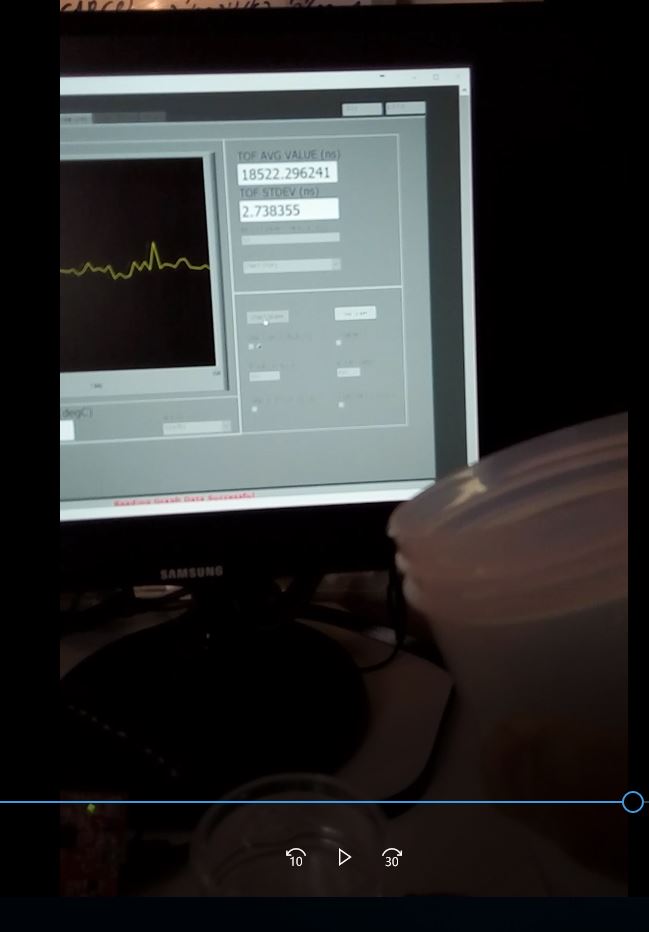
ENABLE_POWER_CYCLE                      00
CLK_FREQ_(1-16MHz)                      8.000000
CLK_SOURCE_SEL                          00
CPU_CLK_FREQ                            05
CPU_CLK_EN                              00
TDC1000-HV_BST_PWR_EN                   00
HV_BST_PWR_EN_Period                    0000
FWD2REV_FLOW_DELAY                      0000
TDC1000-IMPE_MATCH_EN                   00
ENABLE_UART_STREAM                      00
ENABLE_MSP430TIMER_TDC                  00

I would like to shere the results that I had today 

With the TDC1000-TDC7200EVM

I made today experiment  of the  water level

My target today was to see changes of positives numbers  in the TOFAVG   

While I am adding water to can  

But instead of increasing  number of the TOF AVG

I I've got results of decreasing numbers

The  changes were very linear and stable

But in the opposite direction

then in  another experiment

As a continues with my experiments on the EVM

I managed to get the rising of the numbers while I add water

And it made by changing  in the

TIMEOUT(0X8) sector

FORCE_SHORT _TOF  TO ENABLE   in the TDC1000

But   I think that the level  of the water is not affect on the numbers

They increase in the start and then it stay there

No matter what is the water level


  • Hello Ari,

    Forcing short TOF with these settings allows you to measure up to about 10cm. If the level of your water is below this, then this should be fine. Otherwise you should disable short TOF mode and continue with the other timing settings you have.

    From your results it seems that you are not getting a proper return echo. Currently you have the gain set to 0, a single pulse, a mid-range echo quality threshold. You can increase the strength of your transmit signal by increasing the number of transmit pulses. In this case 2 should be fine (this is NUM_TX in  CONFIG0). Additionally, raising the PGA gain to 6dB or more will help you see a better return signal (PGA_GAIN in TOF-1). Finally, you can decrease the magnitude of the echo quality threshold to -125mV (ECHO_QUAL_THLD in TOF-1). For small ranges this should make sure the TDC1000 can actually see the return echo.

    Another possibility is that somehow an echo is returning from a surface early and at a fixed distance. You may be able to test this by increasing the number of stops the TDC1000 generates. Change the NUM_RX (CONFIG1) to 2 STOPS and the number of stops (TDC7200 tab, CONFIG2) to two.This will allow you to continue measuring past the first stop in case it is erroneous. You can view the TOF value for the different stops by changing the display in the graph tab:

    Finally, some of the trouble may come from the way the transducer is mounted to your container. Please review this app note on the proper mounting of a transducer for level measurement: www.ti.com/.../snaa266a.pdf

    Regards,