This thread has been locked.

If you have a related question, please click the "Ask a related question" button in the top right corner. The newly created question will be automatically linked to this question.

IWR1443BOOST: Using IWR1443boost with MSP432 launch pad

Part Number: IWR1443BOOST
Other Parts Discussed in Thread: TIDEP-0091, IWR1443, UNIFLASH

Can I get a phone number of a person who understand IWR1443boost  with MSP432 launch pad. so I can get better help by calling them? I feel TI's support is pretty bad.

Best regards,

Feng Tang

[unlocked 1/24/18]>LE

  • Hi Feng Tang,

    Sorry to hear that you have some unpleasant experience with TI's support. I will send an email to you to get your feedback on how can we improve and get a quick closer on issue with MSP432. I will also look into the threads which you created to understand the gaps in our support.

    Are you in contact with your TI local support?

    Regards,

    Bhavin

  • Yes, I did contact TI local support, no body answer the phone, I can call you or you can call me at 6309694000 ext 6337
  • Can I get a phone number for a person who understand IWR1443boost with MSP432 launch pad, (the person who know TIEDP-009 reference design for level sensing ?), I follow the document add a 0 ohm resistor and downloaded all the software and install them, the document says "unzip the source code provided", I can not find the zip source code, Can you give some help?


    Thanks,
  • Hi Feng,
    We are trying to arrange a call with you. You should be getting information for the same soon.
    Thank you,
    Vaibhav
  • Hi,

    If you open the TIDEP-0091 design guide (TIDUD26), and go to Section 4 (page 15), click on the link under "5. Software Files".  Scroll almost all the way down, and under "Software (2)" you'll see: Power Optimized Level Sensing Demo Software.  This is the link to the zip file.  Or go here:

    www.ti.com/.../tidcde2

  • Hi Dave,
    I place two .ccxml files to the Target configuration, then I click "launch Selected Configuration", then "Connect to the target" icon, the debug are suspended with the message:
    0x00002D36 (no symbol defined".

    Is this normal?

    Thanks!

    Feng
  • Should I continue to other step such as "load the target" or Should I wait the answer from you?

    thanks,
  • Hi Feng,

    Yes, that's correct. For the MSP432, the next step is to click on the "Load Target" icon, then browse to the /Debug folder where the msp_level_sense_demo.out file is.

    To flash the IWR1443's .bin file, you need to use Uniflash as described in step 4 of 3.2.1.1.2 of the design guide.

    Once you have flashed the MSP432 and IWR1443, then you can mate the boards together, connect the USB cable to the MSP432 and start a UART terminal window (as described in 3.2.1.1.3). The menu that appears will hopefully be self-explanatory.

    -dave
  • Thank you very much Dave!
  • Hi Dave,
    I do not have the 5V power cable come with IWR1443boost, is that a special cable?

    Thanks,
  • Another thing - you *can* run the IWR1443's program by itself (MSP432 is not attached). You must use CCS to do this, since otherwise there will be no output from the board. Read section 3.3.2 of the MMWave SDK's user guide. It will tell you how to flash the IWR1443 with a "CCS Debug" image. Once this is flashed (instead of level_sense_demo.bin), you can start a CCS Debug session (using ar14xx_bp.ccxml), "Connect Target" then "Load Target" and specify level_sense_demo.bin. You will need to set a breakpoint somewhere in main.c or demo.c and click "Run". Or, you can point to a line of code, right click and select "Run to Line". For starters, browse to the bottom of demo.c and place a breakpoint before the call to SPI_Transfer. You can then examine the contents of chirp_data to see what the top 3 distances were found.
  • Any 5V 2amp (or greater) power supply will work. The EVM has a standard 2.1mm barrel jack.
  • Thanks Victor, I have the power supply, I just need to find a proper cable with plug.

    Thanks!
    Feng
  • Thanks Dave,
    I will try these tomorrow.

    Thanks,
    Feng
  • Hi Dave,
    I try to flash IWR1443boost, I put Jumper on SOP2, and powered with 5V and mcro USB and load the image as instructed, set COM4 (XDS110 class application/User/UART (COM4), the image loading failed with message "not able to connect to serial port, I sent screen copy to Victor, can you help us on this?

    Thanks,

    Feng
  • Hi Dave,
    Should I "format SFLASH" first before load image?

    Thanks,
    Feng
  • Hi Feng, it sounds like you are doing the correct steps (Step 4 of 3.2.1.1.2 in the design guide). It sounds like you may not be supplying the correct COM port numbers to Uniflash. After connecting power and USB to the IWR1443, try starting Tera Term (or WIndows Device Manager) to confirm the COM port numbers. You may also try unplugging the power cable, wait a few seconds and reattach, then try again in Uniflash.

    And no, you do not need to click on "Format SFLASH", but you should enable the "Format SFLASH Memory during flash" checkmark.

    -dave
  • Hi Dave,
    I double checked many time through device manger,
    port shown:
    intel(R) active mangement Technology-SOL (COM4)
    XDS110 Class Application/User UART (COM4)
    XDS110 Class Auxiliary Data Port (COM34)
    So I put
    COM port: COM4

    I let Victor forward you the screen shot which is not able to post from here

    thanks,

    Feng
  • I checked the device manager settings shown:
    XDS110 Class Application/User UART
    Device type: Port (COM&LPT)
    Manufacture: Texas Instrument In corporated
    location
    settings:
    Bits per second 9600
    Data bits: 8
    Parity: None
    Stop bits 1
    Flow control: None

    Do we need to change the settings?

    Thanks,

    Feng
  • I believe the correct baud rate is 115200. Here is the text for a successful Uniflash session:

    [6/30/2017, 11:18:16 AM] [INFO] Master_R4: Initialization complete.
    [6/30/2017, 11:18:16 AM] [INFO] Master_R4: Flashing process starting...
    [6/30/2017, 11:18:17 AM] [INFO] Master_R4: Connecting to COM Port COM36...
    [6/30/2017, 11:18:17 AM] [INFO] Master_R4: Reset connection to device
    [6/30/2017, 11:18:17 AM] [INFO] Master_R4: Set break signal
    [6/30/2017, 11:18:17 AM] [INFO] Master_R4: Connection to COM port succeeded. Flashing can proceed.
    [6/30/2017, 11:18:17 AM] [INFO] Master_R4: Reading device version info...
    [6/30/2017, 11:18:18 AM] [INFO] Master_R4: note: CONFIG file is added to list of files for download to the device.
    [6/30/2017, 11:18:18 AM] [INFO] Master_R4: ** 3 files specified for flashing.
    [6/30/2017, 11:18:18 AM] [INFO] Master_R4: Checking file C:/ti/mmwave_sdk_01_00_00_04/firmware/radarss/xwr12xx_xwr14xx_radarss.bin for correct header for IWR1443.
    [6/30/2017, 11:18:18 AM] [INFO] Master_R4: IWR1443 device, fileType=RadarSS_BUILD detected -> OK
    [6/30/2017, 11:18:18 AM] [INFO] Master_R4: Checking file C:/Users/a0732826/workspace_v7.1/level_sense_demo/Release/level_sense_demo.bin for correct header for IWR1443.
    [6/30/2017, 11:18:18 AM] [INFO] Master_R4: IWR1443 device, fileType=MSS_BUILD detected -> OK
    [6/30/2017, 11:18:19 AM] [INFO] Master_R4: Checking file C:\ti\uniflash_4.1\deskdb\content\TICloudAgent\win\ccs_base\mmWave\images\ar1xxx_config.bin for correct header for IWR1443.
    [6/30/2017, 11:18:19 AM] [INFO] Master_R4: IWR1443 device, fileType=CONFIG_INFO detected -> OK
    [6/30/2017, 11:18:19 AM] [INFO] Master_R4: !! Files are valid for IWR1443.
    [6/30/2017, 11:18:19 AM] [INFO] Master_R4: Format on download was specified. Formatting SFLASH storage...
    [6/30/2017, 11:18:19 AM] [INFO] Master_R4: -->Erasing storage [SFLASH]
    [6/30/2017, 11:18:19 AM] [INFO] Master_R4: -->Sending Erase command to device...
    [6/30/2017, 11:18:29 AM] [SUCCESS] Master_R4: -->Erase storage completed successfully!
    [6/30/2017, 11:18:29 AM] [INFO] Master_R4: Downloading [RadarSS_BUILD] size [196692]
    [6/30/2017, 11:19:22 AM] [INFO] Master_R4: SUCCESS!! File type RadarSS_BUILD downloaded successfully to SFLASH.
    [6/30/2017, 11:19:22 AM] [INFO] Master_R4: Downloading [MSS_BUILD] size [67492]
    [6/30/2017, 11:19:40 AM] [INFO] Master_R4: SUCCESS!! File type MSS_BUILD downloaded successfully to SFLASH.
    [6/30/2017, 11:19:40 AM] [INFO] Master_R4: Downloading [CONFIG_INFO] size [164]
    [6/30/2017, 11:19:41 AM] [INFO] Master_R4: SUCCESS!! File type CONFIG_INFO downloaded successfully to SFLASH.
    [6/30/2017, 11:19:41 AM] [INFO] Master_R4: Disconnecting from device on COM port COM36...
    [6/30/2017, 11:19:41 AM] [INFO] Master_R4: Flashing instance clean-up initiated...
    [6/30/2017, 11:19:41 AM] [INFO] Master_R4: Instance deinitialized!
    [6/30/2017, 11:19:41 AM] [SUCCESS] Program Load completed successfully.
  • Hi Dave,
    We found Intel(R) SOL also use COM4 , it is same COM4 as XDS110, so we force Intel SOL use a different port, now it load image successfully.
    I move to the next step
    Thanks for your help

    Fengt
  • Hi Dave,
    We do not have Tera Term window, should I down load that for the DEMO?

    Thanks,

    Feng
  • Hi Dave,
    How do I know the IWR1443boost that we hot is Es1, ES2 or ES3

    Thanks,
    Feng
  • Glad you are able to flash the board successfully.

    ES3 is not available yet, so you probably have an ES2. It should have a sticker on the front that says IR1443 or IWR1443. You will be able to tell for sure when you run the demo. If boot takes more than 300ms, you have an ES1.

  • Hi Dave,
    I try one shot measurement, I did not get the measurement results.
    Does this measurement require second option R164 0 ohm (option) installed?

    Thanks,

    Feng
  • The demo requires resistor R102 to allow PMIC_EN control by the MSP432. R164 is optional, but it connects GPIO_0 from the IWR1443 to the launchpad headers. Without R164, you will get the radar measurement, but not the timing measurement. That said, the executables that are provided in the .zip file are built with REPORT_IR_TIME_MEASUREMENTS defined, so the MSP432 will wait for GPIO_0 to go high following IWR1443 boot. If the resistor is not installed, the MSP432 will wait forever, though the IWR1443 has completed the chirps.

    So - you will need to either add R164, or rebuild/reflash at least the MSP432 image with REPORT_IR_TIME_MEASUREMENTS *not* defined. If this seems confusing to you, perhaps your firmware engineers could take a look.
  • Hi Dave,
    We add 0 ohm resistor for R164, I take one-shot measurement, and still not get any measurement. for more than a few minutes.
    Do you know why?
    Thanks,

    Feng
  • The one-shot measurement never come back, no measurement results with R164 0 ohm installed.
  • The unit draw 310mA, MSP432 green LED is on, IWR1443boost red and orange LED is on, I push "reset" before take a measurement, I still do not get any measurement
  • How do I know the units functioning properly?

    Thanks,

    Feng
  • Did you remove the jumper from SOP2?
  • Okay, so if you see the MSP432's menu appear in the UART terminal window, you can assume that it has been flashed correctly. So, if SOP2 is not jumpered, and the two boards are correctly mated, and the IWR1443 is correctly flashed, it should work.  Unless of course R102 and R164 are not soldered onto the correct locations or not soldered completely.

    When the boards are mated and the MSP432's USB is connected (green LED is on), when you attach the 5V plug to the IWR1443, the red 5V LED should turn on (this is the 3rd LED from the top).  If you attach the 5V plug when the MSP432 USB is *not* connected, the red 5V LED and the yellow NRST should light.  If this happens, I think it's safe to assume R102 is attached properly.

    Also, from initial powerup state (red 5V LED only is on), you should be able to press "w" and see NRST and NERR_OUT turn on, and then press "p" and see them turn off.  This also means that R102 is good.

    The only way I know to prove that R164 is not good is to either: 

    1) reflash the board with the CCS debug image as I described above (see the MMWave user guide), then load the level_sense_demo.xer4f file to the IWR1443 from the CCS debugger.  If you can run to the bottom of demo.c that means the image does run to completion.

    2) rebuild the IWR1443 image with REPORT_IR14_TIME_MEASUREMENTS not defined.

    I am attaching pictures that show the locations of the two resistors, just to make sure.

    evm_mods.zip

  • Hi Dave,
    I checked R102 and R164 are in the right location, it seems R164 not soldering properly, I resolder R164, now I launch Tera term, it can not open COM5, I measured between R164 to J6 pin 15 is 0ohm. Do you know what happened?

    Thanks,
    Feng
  • Not sure I understand. R164 populated or not, should not have an effect on the COM port of the MSP432...
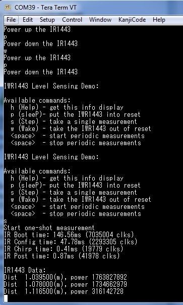
  • Can you give me screen picture what MSP432's MENU appear in the UART terminal window?
    I separate MSP432 and IWR1443 boost with the mcro USB connect to MSP432 only and launch Sera Term, the COM5 (XDS110 class application/Uer UART port) still can not open
  • There's a picture in the design guide, here's another one (below). The UART portion of the MSP432's program will work whether or not the IWR1443 is attached.

  • Hi Dave,
    When I plug micro USB to MSP432 board only, only the green LED on MSP432 board is light; when I disconnect mcro USB from MSP board and add 5V to IWR1443 boost board, the red LED DS2 (third one) and yellow NPST is light, when I plug micro USB to MSP board and add 5V to IWR1443 board, the green LED on MSP board is light, the two RED LED DS1 and DS2 (second and third) is light, the NPST Yellow LED also light, if I push rest button on MSP board DS2 red LED on IWR1443 is off, DS1 RED LED (third) and NPST is light. All of these with R164 is not installed, the Tera window show S, P, S, W, Space , Space menu; after installing 0 ohm on R 164, Tera window menu disappear, "can not open COM5" message are appear. I re flash both MSP board and IWR1443 board, I still get the message "can not open COM5", I remove R 164 again, the MSP menu appear again, do you know why?????
  • Hi Dave,
    I get the boards running, thanks for the help!
  • Glad to hear it!
  • Hi Dave,

    I got the board running on Monday, I could measure the three distances and saw the MSP menu, today I connect to the power, micro USB to MSP, 5V to IWR1443, the MSP window disappear again, all the leds running properly, when power to MSP board, only green LED on MSP is on, Apply 5V to IWR1443 and micro USB to MSP432, the red LED (third one) and the green LED on MSP are on. I reflash MSP and IWR1443, the MSP menu still can not bee seen, I click "connection" in Tera window, I can see COM5:XDS110 Class Application/User UART COM5), I select this port and click ok, I still do not see MSP window. Do you know why?

  • Hi Feng,

    It sounds like you may be having problems on the PC side (with the UART port). If you see the COM port as described and configure it properly (I'm talking about Tera Term here), then press the MSP432 reset button you will see the menu. If you don't, I would suspect the COM port configuration. You may also try a different PC.
  • Hi Dave,
    I try to power on and power off 5V many times, only one times the MSP menu shows up and measure the three distances, I power the device off and on again, the msp window disappear again, Push MSP reset, it show Ʃ. ᷉XnNZ:
    Do you ever see this?

    Thanks,
  • Hi Dave,

    I use the default configuration and put the target around 0.1 m(100 mm), the three measured distance are: 1.3860 meters, 1.3475 m, 4.3890 m, if I move the target further close to antenna <0.1 m, the measurement results never come back, do you know the reason?

    Thanks,

  • Hi Feng,

    The default configuration is not designed to work < 1m, though it works fine down to 0.5m.

    -dave
  • Hi Dave,
    Do you have configuration that is work from 0.1 meters to 40 meters?

    Thanks,
    Feng
  • Hi Dave,

    I use the default configuration and take the distance measurement at our radar range, our radar range is for our radar sensor calibration, which have a calibrated laser distance measurement, here are the data, the largest measurement error of IWR1443 Dis1 (compare to laser measurement) is 1059 mm, it is very big, do you know why?

    TI IWR1443boost 77GHz to 81 GHz Radar chip evaluation board

    Measured at Radar range of Engineering Lab

    Laser measurement

    IWR1443boost (mm)

    Power

    Laser-Dis1

    Distance (mm)

    Dis1

    Dis2

    Dis3

    at Dis1

    Delta (mm)

    21310

    20250.9

    20212.5

    20189.5

    57307321

    1059.1

    19879

    19827.5

    28259

    19789

    51.5

    18670

    18595.5

    18634

    28259

    178752654

    74.5

    17195

    17132.5

    17171

    170940

    476095629

    62.5

    15551

    15477

    28259

    15592.5

    74

    14203

    14129.5

    14360.5

    14168

    73.5

    13277

    13205.5

    13167

    13244

    901627212

    71.5

    12314

    12243

    12204.5

    12281.5

    197127742

    71

    11111.9

    11165

    11126.5

    11203.5

    380750605

    -53.1

    9896.4

    9817.5

    10048.5

    19712

    78.9

    9063.3

    9240

    9278.5

    8970.5

    157853296

    -176.7

    7906.8

    7815.5

    7854

    77777

    672373668

    91.3

    7008.2

    6930

    6891.5

    6968.5

    1027425528

    78.2

    6178.7

    6083

    6121.5

    6044.5

    1678568395

    95.7

    5176.6

    5082

    5120.5

    5043.5

    1538365768

    94.6

    3989.6

    3888.5

    3927

    3965.5

    -1744579788

    101.1

    3073.6

    3003

    2964.5

    3426.6

    -1292528667

    70.6

    2604

    2502.5

    2541.5

    2464

    -580423179

    101.5

    1754.1

    1694

    1617

    1732.5

    -1423123201

    60.1

    1274.5

    1155

    1193.5

    1232

    -1213862908

    119.5

    825

    can not measure

    #VALUE!

    783.1

    693

    654.5

    731.5

    -186600898

    90.1

    652.4

    577.5

    539

    3041.5

    -2076784608

    74.9

    486.9

    385

    423.5

    2194.5

    1868245060

    101.9

    349.8

    539

    577.5

    269.5

     Thanks,

    Feng

  • At this point, you need to consider your design requirements and create a chirp configuration that suits your needs for range, accuracy, power, etc. etc.  This demo (like the mmw demo) cannot support all chirp configurations and may require modification for your needs beyond simply plugging in a new chirp config. That said, the existing chirp configuration makes several compromises, and we are currently working on several aspects of the demo to reduce run-time and power consumption.

    I can point you to several resources:

    The Sensing Estimator (chirp config calculator)

    https://dev.ti.com/gallery/view/1792614/mmWaveSensingEstimator/

    Threads/information on sub-mm accuracy with mmWave devices:

    https://e2e.ti.com/support/sensor/mmwave_sensors/f/1023/p/599055/2206436#2206436

    https://e2e.ti.com/support/sensor/mmwave_sensors/f/1023/t/597434

     (or simply type "resolution" into the Search bar while in the mmWave E2E forum).

  • Since the reason for this thread has been answered (you are able to run the demo), I am going to close this thread. If you have performance/chirp questions, you may open another thread.

    Thanks, dave