This thread has been locked.

If you have a related question, please click the "Ask a related question" button in the top right corner. The newly created question will be automatically linked to this question.

IWR1443BOOST: Elevation angle estimation evaluation questions

Part Number: IWR1443BOOST
Other Parts Discussed in Thread: IWR1443, UNIFLASH

Hi

I am currently using IWR1443BOOST in combination with TSW1400 data capture card to evaluate the elevation beamforming performance and I have three questions regarding this issue.

I want to use a multiple chirp configuration, which I use to switch between each Tx to get a filled MIMO array according to http://www.ti.com/lit/an/swra554/swra554.pdf.

I currently use a chirp sequence of three chirps with Tx1,Tx2,Tx3 sequentially activated, with 64 chirps in each frame. 

How is the data arranged when using multiple chirps. Does chirp 2 is the picture below belong to the chirp 1 in configuration 2 or does it save it as chirp 2 in configuration 1?

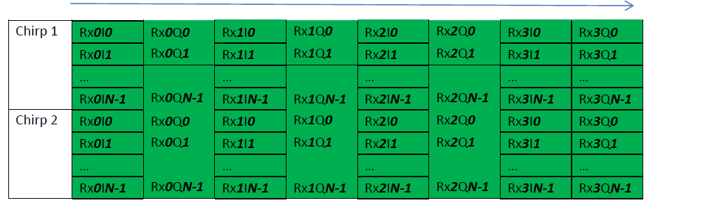
1, How is the data arranged, so I know how to correctly read it meaning knowing how the data arranges in a multiple chirp configuration recording file?

2, Are you going to support elevation estimation in a future version of the Radarstudio postproc program?

3, Which Tx,Rx in Radarstudio corresponds to which antenna on the IWR1443 so I know how to sort the incoming data in correct order for beamforming?
I have guessed the following order shown in the picture below but I haven't found out if it's correct.


Thank you,

Karl Nordin

  • Hello Karl,
    The output data format from TSW1400 shown in the figure above is in the order of the chirps transmitted. If you use TX1 in chirp 1 , TX2 in chirp 2 , TX3 in chirp 3, then output data would in the same order -> chirp 1 (TX1) - chirp2 (TX2)- chirp 3 (TX3)- ...
    The order of the TX and RX antennas you have indicated above is correct. We will update our EVM user guide to have this indication as well for the easy identification in the future.
    For the elevation estimation you can refer to the mmw demo application in the mmwave SDK for an example post processing.

    Regards,
    Vivek
  • Hello Karl,

    The output data can be arranged in the CSI block for output.   When I did the processing, I used the attached Matlab scripting.

    In my case, we would build an MSS image, using Uniflash (EVM separate from Devpack) to program BSS and MSS images.

    We would then reassemble EVM to Devpack.   In Radar Studio, we set SOP mode to 4, Reset the device.

    We then go to TSW1400, load the approriate firmware.

    We then set the ADC out rate to 11.25Msps.

    You set the TSW1400 output file location, under options you need to save the appropriate amount of data,  and depress capture.

    You then use the matlab script to post process the results.

    One of the key components, is that if you have 128 chirps for each Tx, with 3 Tx you have 384 total chirps in the frame.  In the TSW output processing you have to save enough data.

    If you do this within Radar Studio, the EVM flash is blank.

    You use the appropriate BSS and MSS image from the instructions, and setup the parameters.

    You still need to size the data option size in TSW1400 though.

    So post processing can be done externally if you want to do your own post processing.

    I will ask the matlab script author about post processing elevation.

    Regards.

    Joe Quintal

    read_Post_process_ADC_Capture_data_LVDS.zip

  • Hello Karl,

    The post processing step in Radar Studio take the raws ADC data and runs it through FFT processing on per receiver/channel basis.
    As such it is not cognizant about the data from that specific receiver being relevant in terms of Azimuth or elevation.
    We do not have plans to add such classification to post processing steps, you can always do the custom post processing as provided in Joe's response.

    Thank you,
    Vaibhav
  • Hi Radio-Joe

    Thank you for your answer.
    I will look at it what you suggested.

    I have done a similar matlab script to read the data file into matlab like the one you linked to, but realized it had an error when a saw your code.

    As you suggested I have done the postprocessing algorithm to evalute. The most important at the moment is that my reading into matlab is correct, so i can perform the post-processing algorithm correctly.

    What I mean by correctly is that i can sort the data into a matrix knowing (data_adc_sample, Chirp number, Virtual antenna, Frame).

    When this is performed correctly it should be no problem for me to do the post processing steps to evaluate the elevation beamforming since I already have the post-processing algorithm to perform this, but it would be interesting to see how you perform the elevation post processing.


    Thank you,
    Karl Nordin
  • Thank you for your information.
    Will take a look at the mmw demo application to verify my current algorithms.

    Regards
    Karl