This thread has been locked.

If you have a related question, please click the "Ask a related question" button in the top right corner. The newly created question will be automatically linked to this question.

IWR1642: question about TestPattern in test_adcbuf.c

Part Number: IWR1642

Hi,

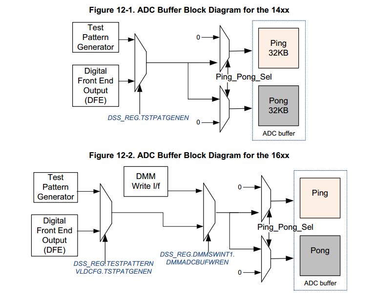
In C:\ti\mmwave_sdk_01_00_00_05\packages\ti\drivers\adcbuf\test\common\test_adcbuf.c, it seems that ADC buffer can output test pattern for debug purpose.

What is the detail data in this test pattern? Are they random data? Can the test pattern to be user defined? My customer wants to send a known data from adc buffer to LVDS for debug purpose.

  • Chris,

    The TRM for the IWR devices provides information on the test pattern generation capabilities of the ADC Buffer. I have linked to this document below:

    An explanation of the test pattern generator can be found on page 1118. Additionally, the register definition for TESTPATTERNVLDCFG which is used to configure the test pattern generator can be found on page 561.

    Finally, Figures 12-1 and 12-2 provide a good visual explanation for how the test pattern generator works.

    Please let us know if you need any additional information.

    Regards,
    Kyle

  • Kyle,

    Thanks for your info! With your help, I found below code can configure the test pattern.

        /* Configure Test Pattern generation */
        testPatternConf.period = 255;
        testPatternConf.numSamples = sample;

        for (channel=0; channel < 4; channel++)
        {
            testPatternConf.rxConfig[channel].rxIOffset   = 0x0;
            testPatternConf.rxConfig[channel].rxIInc       =  0;
            testPatternConf.rxConfig[channel].rxQOffset  = 0xffff;
            testPatternConf.rxConfig[channel].rxQInc      =  0;
        }

    But I still have question. What is the period for? As we uses continuous mode for test pattern, the test pattern will repeat continuously. This param seems no useful.

    I also tried to capture the LVDS data by TSW1400 with High speed data converter Pro. But I found the first bit of the 16-bit data is inverted. That is, if I set pattern as above code, I got data with 0x8000, 0x7fff, 0x8000, 0x7fff. Why the first bit is inverted? My setting of High speed data converter Pro is as below. I changed the output data rate in HSDC Pro, but it seems no effect.

    The continuous mode config I used is same as capture_demo_script_lvds_cont_mode.txt in sdk 1.0 capture demo for xWR1642 folder.

  • Hi,

    Any comment on the invert bit? Is there anything wrong on my setting in HSDC Pro to make this invert?

    I also found there is garbage data in the RAW file I saved by HSDC Pro between the valid sample data. For example, if I set the testPatternConf.numSample=1024, I can see garbage data between every 1024x4 bytes data. Is this normal?
  • Hi,

    Any comment on the invert issue?
  • Hi Chris,

    I am looking into this issue. I am running the capture demo with the test pattern you generated and am trying to trace the data all the way through to the HSDCPro capture to hopefully see where the bit is being flipped. Also, I am using the same configuration you did to ensure that our setups are exactly the same. 

    Quick question, just to verify, when running the Capture Demo do you select :Option #3: MSS is responsible for Control Path and DSS is responsible for Data Path" or one of the other options?

    Regards,
    Kevin
     

  • Hi Chris,

    Update, I am now able to reproduce your results and also see the inverted bit. Furthermore, I can also verify that the ADC buffer data is correct in both the MSS memory and DSS memory. I am currently playing around with the code and trying to trace the data all the way through the LVDS to the TSW1400 in order to hopefully find where it is being flipped.

    Regards,
    Kevin
  • Kevin Ortiz said:
    Quick question, just to verify, when running the Capture Demo do you select :Option #3: MSS is responsible for Control Path and DSS is responsible for Data Path" or one of the other options?

    I always tried with option 3.

  • Hi Chris,

    That is what I assumed. Thank you for confirming. To offer a quick update:

    There was some small confusion on our end when we tried to set the offsets and increments of each channels to unique values so that we could identify which packet was coming from which channel. After a quick look at the SDK User's Guide, we realized only channel 1 was being enabled in the config file.

    Next step, is to increment the packets coming from channel 1 by by 1 so that hopefully match each value on the ADC buffer to the values captured on the TSW1400.

    We are also looking into possibly scoping the physical LVDS line itself in order to see whether the bit flip occurs before or after the LVDS transmission.

    Regards,
    Kevin
  • Hi Chris,

    We finally got some insight on why the MSB bit is being flipped. The .ini file in HSDCPro (in this case: AWR16xx_lvds_4Channel_ddr_4bit_par_centre_16_bit.ini) basically adds 0x8000 to every value received. This explains why the MSB bit is always flipped from what we expect. We are currently looking into what the purpose of this is and if it's possible to disable it.

    Regards,
    Kevin

  • Kevin,

    Thanks for your help! Good to know that we have found the cause of the bit flipped. Wait for your further update.
  • Hi Chris,

    Upon further investigation, we learned that the specific line in the .ini file that is responsible for the bit flip is "Data Postprocessing=1:32768"

    This line is required for the HSDC Pro to display (process and plot) the captured data. If you simply remove the above mentioned line, the bit flip no longer happens.

    Be advised, removing the line will cause PostProc to fail when using RadarStudio. RadarStudio essentially reverses the bit flip in order to display correct data.


    Regards,
    Kevin