This thread has been locked.

If you have a related question, please click the "Ask a related question" button in the top right corner. The newly created question will be automatically linked to this question.

IWR1443: confusing of sampling rate

Part Number: IWR1443

I am using IWR1443BOOST->DEVPACK->TSW1400EVM to do some test. I want to do some data processing from the data captured from TSW1400.

But I am confused about the sampling rate.

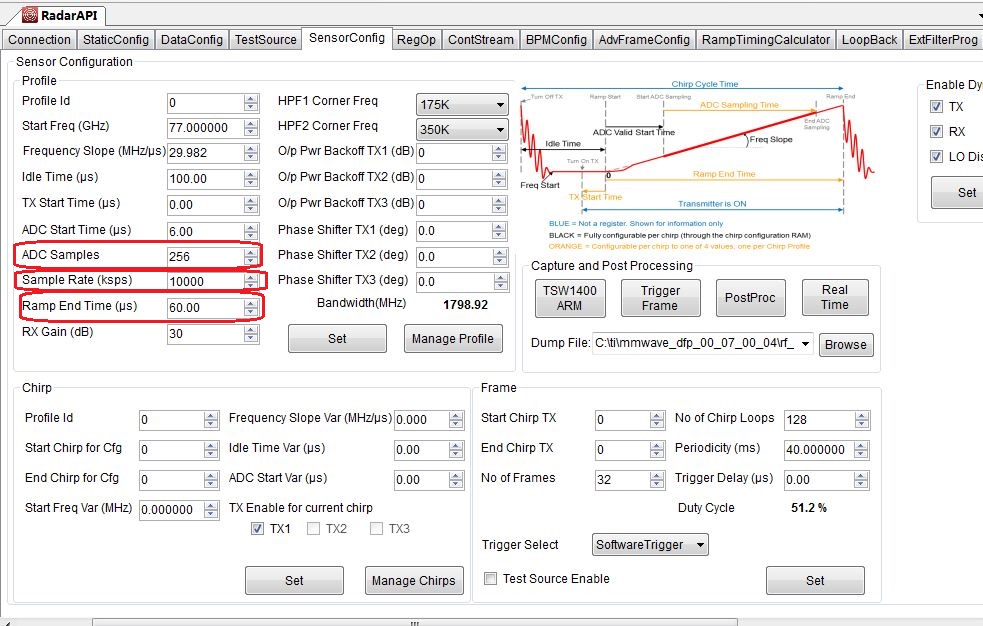
In 'SensorConfig' of RadarStudio, ramp end time is set as 60us, and sample rate is 10000ksps. So, samples before ramp end time should be 600.

Question 1:

What is the meanning of 'ADC samples' in SensorConfig?

As the sample rate is 10000ksps, after I press TSW1400 setup, the sample rate in HSDC Pro is set as 7.5M.

Question 2:

What is the relationship between these two settings?

Question 3:

I want to analyse data captured from TSW1400, how can I know the number of sample in one FMCW period?

Thanks,

Zhaoyu

  • Hello,

    Q1) When we setup Radar Studio, the Chirp Design, needs to be done through the external mmWave Estimator and/or the Chirp calculator spreadsheet.

    ADC Samples – this is the number of DFE output samples per chirp

    Sample Rate – this is the DFE output rate in ksps

    RampEndTime – this is ADC Valid Start time + (ADCsamples/chirp / Sample rate) – the ADC Valid Start time depends on the desired settling time, then the Ramp end time is computed.

    In Radar Studio, select the Ramp Timing Calculator, enter the rampt timing inputs from your chirp design.   In the Recommended Configuration, the Idle time, ADC Start Time, and Ramp End Time are copied to the Sensor Config tab.  Typically the 95% or 99% settling time is used.

    Q2) The 7.5M is the start setting for the TSW1400 Clock input PLL, it is multiplied by a value.   Under the Radar Studio Data Config tab the Data Configuration, selects the LVDS output data path, formatting.

    Typically - LVDS, Packet 0 ADC_ONLY, Packet 1 Suppress Packet

     DDR Clock, Data Rate  - depends on the DFE output rate, typically we use one DFE output per LVDS data lane, so with Complex data, 16bit rounding, we have  

    32bits/IQ sample * 256 samples/chirp * 10000ksps * 1 Rx/LVDS lane = 81.92e9 bits/chirp, with a DDR clock the LVDS transmit period is 81.92e9bits/(2*600e6) 

    the DDR clock has to be fast enough to output the LVDS data set over the chirp period.

    Q3)   Under the Sensor Conf tab, the Sample rate (DFE output rate), and ADC samples + ADC Start time are programmed as the Ramp End Time.

    in this example 256/10e6 + ADC Start time ( from Ramp Timing Calculator 99% settling)  + Excess Ramp Time <= Ramp End Time  , a rule of thumb is that ADC Start time, matches Excess Ramp time.   

    In the Sensor Config, we typically tell the TSW1400 through the number of frames, the number of chirps/frame * frames to collect.  This information is past through the POST PROC button to the matlab post processing script.   0 is considered continuous, I use 10 frames.  Radar Studio programs the data amount when we arm the TSW1400.

    The dumpfile contains the path and filename that is stored for analysis.

    Regards,

    Joe Quintal