This thread has been locked.

If you have a related question, please click the "Ask a related question" button in the top right corner. The newly created question will be automatically linked to this question.

LDC1614EVM: Coil Characterization Data

Part Number: LDC1614EVM
Other Parts Discussed in Thread: LDCCOILEVM, , LDC1614

Dear Technical Support Team,

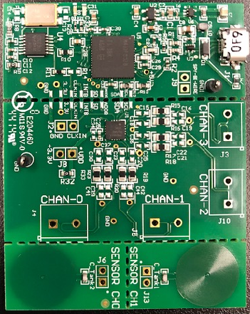
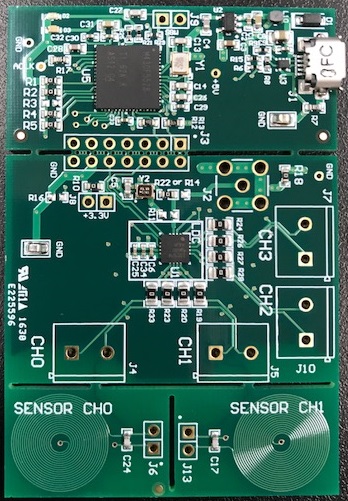
Could you share the Coil Characterization Data of LDC1614EVM like LDCCOILEVM?

It has default coils for ch0 and ch1.

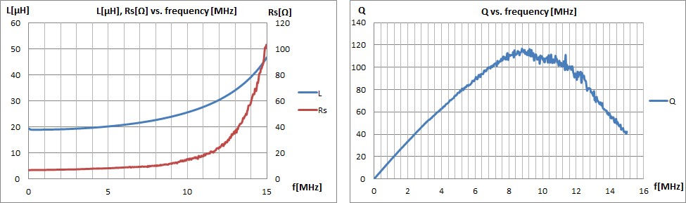
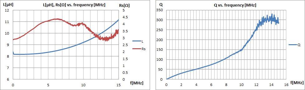
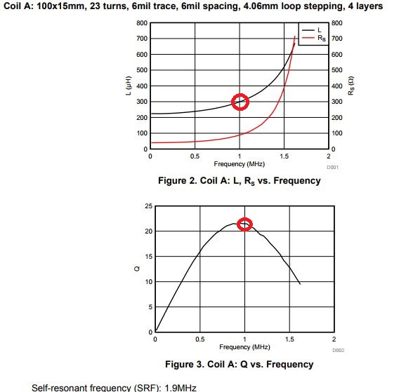
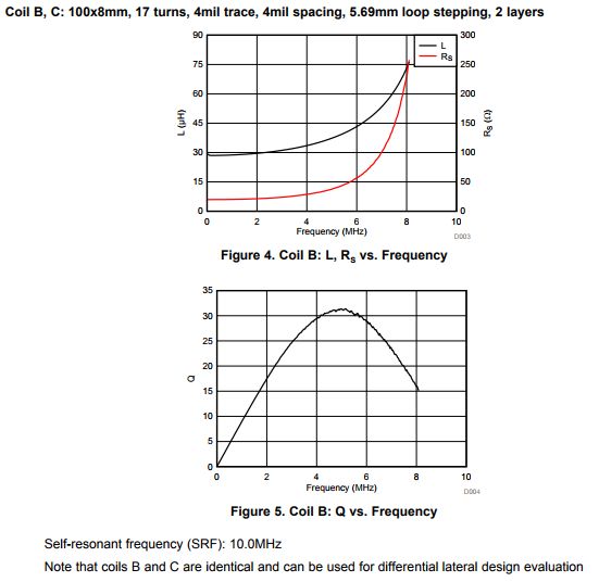
I'd like to know graphs of "L, RS vs. Frequency" and "Q vs. Frequency" for these like below.

Best Regards,

ttd

  • Hello,

    There are two revisions of the EVM, which are labeled as Rev A and Rev B. All EVMs acquired from the e-store should now be Rev B versions, but if you happen to have an older Rev A board I will include that data as well.

    LDC1614EVM RevA (Front and Back View):

    LDC1614EVM RevA, Coil specification:

    Nominal inductance = 18.9 µH

    Diameter: 14.0 mm

    32 turns/layer

    2 layers

    0.10 mm (4 mil) trace width

    0.10 mm (4 mil) trace spacing

    1.6 mm (62 mil) total PCB thickness

    LDC1614EVM RevB (Front and Back View):

    LDC1614EVM RevB, Coil specification:

    Nominal inductance = 8.2µH

    Diameter: 13.9 mm

    19 turns/layer

    2 layers

    0.15 mm (6 mil) trace width

    0.15 mm (6 mil) trace spacing

    1.6 mm (62 mil) total PCB thickness

    Regards,

    Luke LaPointe

  • Hi Luke,

    Thank you for your reply.

    It's good reference for me to calculate  capacitor value of LDCCOILEVM.

    Why did you selected 3MHz for sensor frequency for LDC1614EVM revB ?

    According to  your attached graphs ,    the frequency is approximately 3MHz when L is 8.2µH.

    For example , I think that 5Mhz is better than 3MHz for sensor frequency,

    because Q of 5Mhz is high than 3Mhz's one and 5Mhz is center frequency of 10MHz(LDC1614's max freq).

    And other question, I tested the variation of frequency while the target is approaching the coil, the frequency is increasing from 3Mhz.

    Is it possible to decrease the frequency when the target is approaching the coil?

    I concerned much lower frequency isn't good for Q based on your attached graph.

    In case of type A(LDCCOILEVM) , I selected 1MHz and it is the highest point of Q below.

    But Q of LDC1614EVM's coil doesn't have the highest point of Q(Q is only increasing as the frequency is increasing). 

    Best Regards,

    ttd

  • Hello,
    When looking at these coil measurements it is important to keep in mind that the inductance is back-calculated from the impedance which increases with frequency because there is parasitic capacitance from the coil. You can use this information to determine both the self-resonant frequency (SRF) of the coil as well as its parasitic capacitance. However, if you were to model this coil as an RLC circuit, you would use the inductance value at low frequency as your L value and not the back-calculated one which changes over frequency. Then when you add a discrete capacitor, you should pick a value that sets the sensor frequency below the SRF to maintain a stable operation. If you calculate the Q factor, it should be based on the discrete capacitor value you add, the inductance value, and the parallel resistance of the circuit at the resonant frequency.
    Regards,
    Luke LaPointe