This thread has been locked.

If you have a related question, please click the "Ask a related question" button in the top right corner. The newly created question will be automatically linked to this question.

RE: TDC1000-GASEVM: TDC1000-GASEVM

Other Parts Discussed in Thread: TDC1000Hi Scott,

I have several questions:
1、In the TDC1000-GASEVM board,the R42/R43=0,while in TDC1000-7200EVM board, they are C42/C43=300pF, I read the TDC1000 datasheet,I also find they are 300pF or 900Ω,I don't know why they are 0 in GAS-EVM.
2、If I want to drive 40KHz Ultrasonic transducer, what parameters do I need to change in the TDC1000-GASEVM?
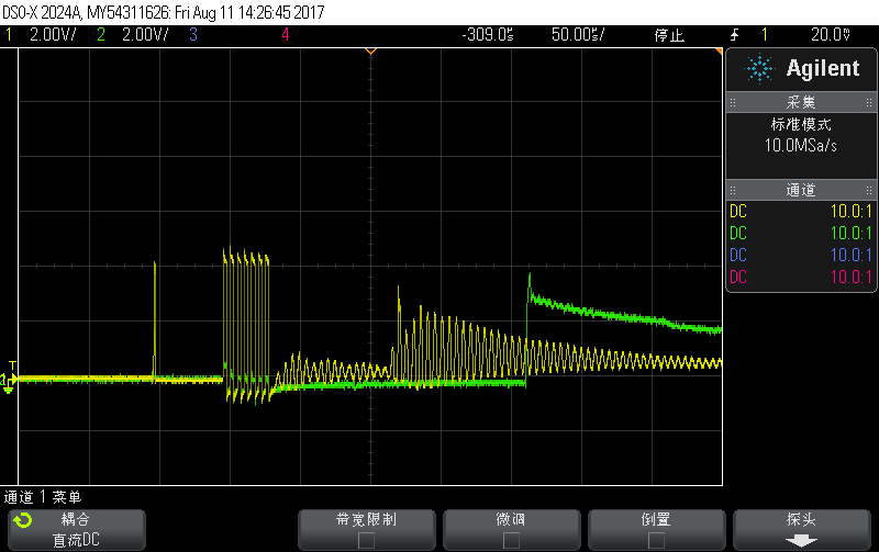
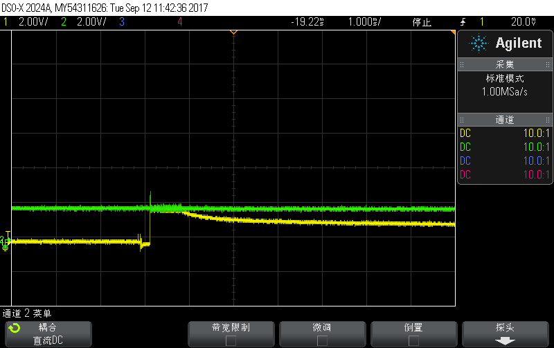
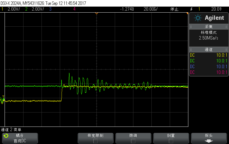
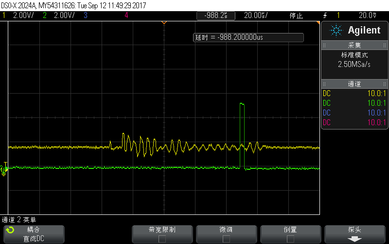
3、I am measuring time-of-flight between two 200KHz Ultrasonic transducer by TDC1000-GASEVM + BST evm(The driving voltage is 30V), I found that the receiver signal RX1 is the same whether or not it has access to the receive sensor. I use CH1(TX1) and mode1, so the channel should is TX1/RX1.

please help.

thanks,

Lee
  • Hello,

    1. When in development the board was originally designed to be used with resistive feedback mode on the LNA, but later we started recommending using the capacitive feedback mode. It should work fine as it is, but for best performance in capacitive feedback mode I would change the components to match the application diagram in the datasheet (using 300pF caps on the inputs).

    2. You will need to change the bandpass filter components between the PGA output and COMPIN (R34, C27, C32, R31). I don't have a suggested filter design for this at the moment. You can test some designs out using something like TI TINA. It is a simple RC bandpass filter.

    3. They should not be populated, but just double check that there is nothing on the board for R41 and R52. If you have CH1 selected, that will be TX2/RX2 in mode 1. Are you saying that even with the transducer disconnected you are seeing a signal on RX1?

    Regards,
  • Hello,

    In view of the above third points,I checked  that there is nothing on the board for R41 and R52. If I have CH1 selected, that should not  be TX1/RX1 in mode 1?And  that even with the transducer disconnected I saw a signal on RX1, the signal is same as that with the transducer connected.

  • Sorry for the confusion. That diagram is correct, I was thinking in terms of the channel select bit instead of the channel number. In mode 1 channel 1 (Ch sel = 0) is TX1/RX1, and channel 2 (ch sel = 1) is TX2/RX2 as shown above.

    And what do you see on the COMPIN pin with nothing connected?
  • Hi,

    What I see is as follows with channel 1(TX1/RX1):

    1、With RX ultrasonic transducer connected, there are signals :RX1,COMPIN and  STOP

    2、Without RX ultrasonic transducer connected,there are signals:RX1(the signal is same as 1)  ,but I didn't see COMPIN and STOP signal;

    Without RX1 ultrasonic transducer connected:

    In this picture,yellow-RX2,   green-RX1(I don't understand);

    In this picture,yellow-RX1,   green-COMPIN, no STOP;

    With RX1 ultrasonic transducer connected:

    In this picture,yellow-RX1,   green-COMPIN;

    In this picture,yellow-RX1,   green-STOP;

    In this picture,yellow-COMPIN,   green-STOP.

    I wonder if this waveform is correct,please.

    Thanks,