This thread has been locked.

If you have a related question, please click the "Ask a related question" button in the top right corner. The newly created question will be automatically linked to this question.

AWR1243: IF Loop Back Beyond 10 MHz

Part Number: AWR1243

Hi, 

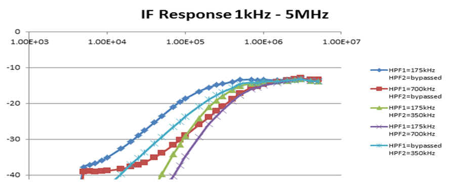
From the AR1xx_Radar_Interface_Control document, the maximum IF loop back frequency is 10 MHz and the minimum IF loop back frequency is 180 kHz.

Can the minimum be less than 180 kHz (start from 10 kHz) and the maximum increased beyond 10 MHz ?

Regards,

RJ 

  • Hello,

    The radar sensor has different operating modes, and the signal bandwidth is based on the Digital Front End (DFE) output rate.  The signal bandwidth is also limited by the HPF1, HPF2 high pass filter selections in the ProfileCfg.   The green and purple plots in the attached figure show the two lowest HPF filter settings.  

    Note: in the graph, we apply more than 40db attenuation to the Rx signal based on the High Pass Filter selection.   The Rx LNA gain adds 24 - 48db, to eachRx.    So the High Pass limit would be based on the air attenuation, and reflection to the antenna.   In the case of measuring close range objects this is one part of the configuration.

    The Digital Front End (DFE) provides the filtering, decimation, and digital tuning of each Rx-ADC set of outputs.  In the Complex 2x, or Real modes, the low frequency of the DFE filtering is 0.   In the Complex 1x mode, the low frequency is limited by the digital filter, about .05 * DFE output rate.

    The highest DFE sample rates are based on the DFE output rate programmed.   This is also dependent on the DFE mode.

    Real mode, DFE output rate is 2.5 to 37.5Msps; DFE bandwidth is 0 to .45*DFEout rate.

    Complex 2x mode, DFE output rate is 2.5 to 18.75Msps; DFE bandwidth is -.45*DFEoutrate to .45*DFEoutrate.

    Complex 1x mode (freq shifted), DFE output rate is 2.5 to 18.75Msps; DFE bandwidth is .05*DFEoutputrate to .95*DFEoutput rate 

    Note: this is based on the DFE digital filters having a 90% passband for the final filtering.

    Regards,

    Joe Quintal

  • Thank you, Joe for your detailed response.

    I followed your reply and I understand your reasoning as well.

    If I am trying to evaluate the baseband frequency response once the chip is in a product and want to make sure that my HPF/LPF are behaving as expected, then I think it makes sense to loopback across the entire pass band and attenuation band to make sure I am getting the attenuation as expected.

    I was hoping that I can use the IF loopback feature for in product testing and characterization. In complex 1x, if my max IF is 15 MHz, I would need to loop in beyond 10 MHz if in 1MHz steps till I cover entire baseband.

    Do you suggest any other approach to quantify the baseband frequency response performance ? At the waveguide interface level, it is simpler because I can inject a tone myself.

    Regards,

    RJ
  • Hello,

    You can fix the Tx chirp frequency to "A".  You can then use an external generator to sweep over the desired range of frequencies.   There are two types of sweeps

    RF center frequency, to characterize the transmitter and RF range of the receiver.  At specific RF frequencies you can use different Chirp DFE output bandwidth and externally attenuated RF tones to characterize the mixing, HPF1, HPF2, DC Removal, and the DFE filtering effects.   Complex 1x 2x modes have a bandpass, while real mode has a Low Pass for DFE.

    Note: using attenuation of test-Rx input, you can also check the Rx LNA range.

    Regards

    Joe Quintal

  • Thank you Joe for your reply. I appreciate your help.