This thread has been locked.

If you have a related question, please click the "Ask a related question" button in the top right corner. The newly created question will be automatically linked to this question.

AWR1443: Complementary informations & Bragg patterns

Part Number: AWR1443
Other Parts Discussed in Thread: AWR1243BOOST, AWR1642, IWR1443, AWR1243

Hello,

For  a personal project I'm considering using an AWR1443 (or other AWR if they can fit my needs).

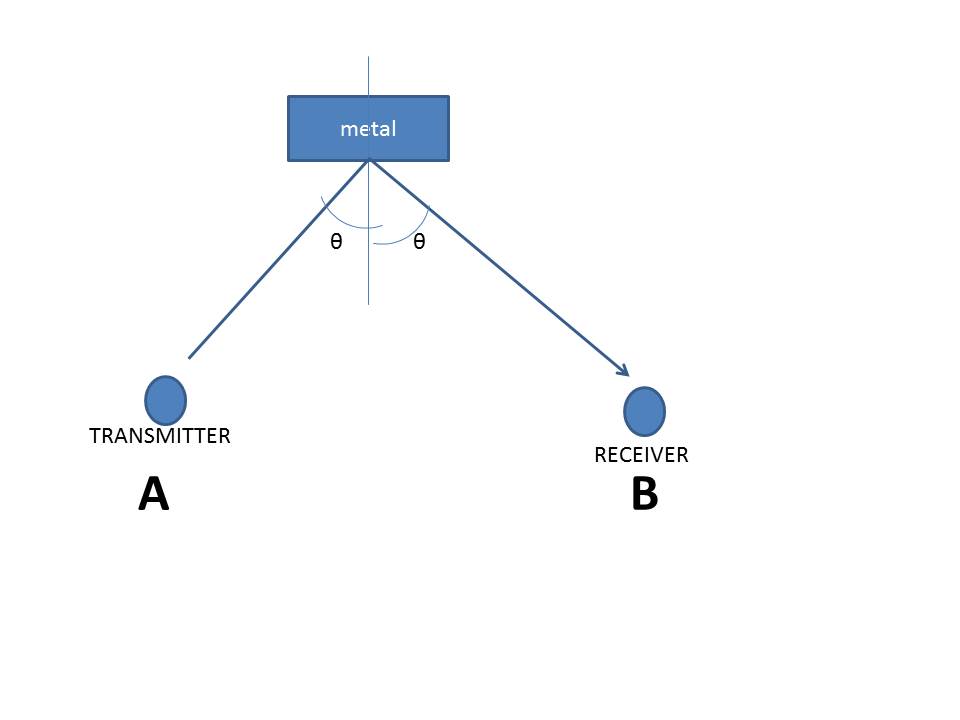
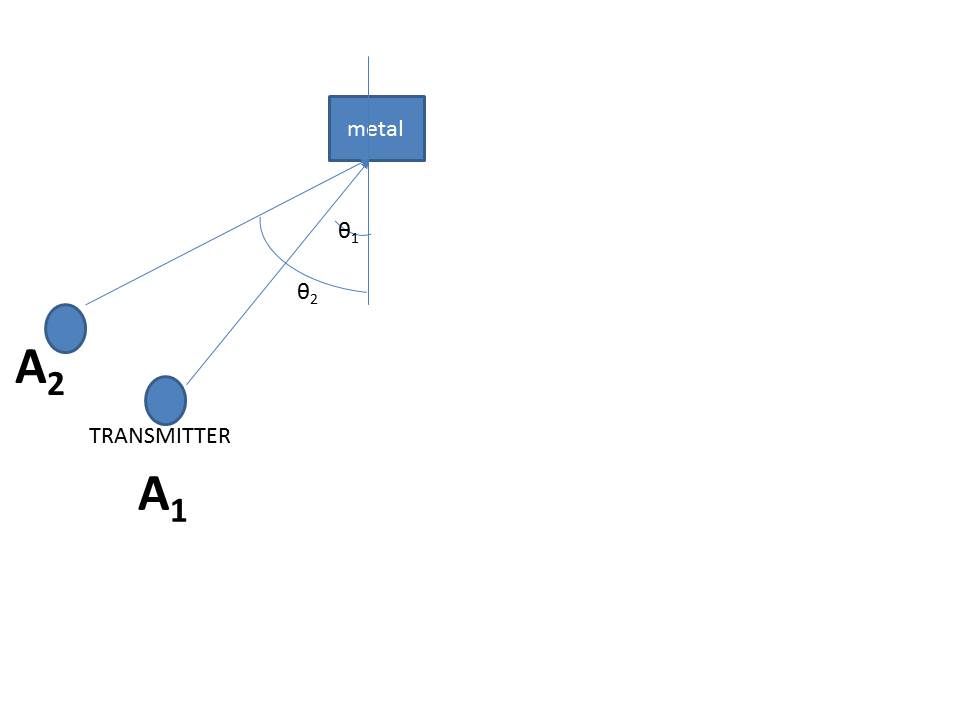
My goal is to detect Bragg patterns at 5~20m away from the radar.

As a reminder Bragg pattern follow Bragg's low of diffraction as 

Theta_n = Asin(n * Lambda / 2 * Surface_periodicity)

As my surface periodicity is L = 0,5 cm an millimeter wave radar should be able to detect it.

Is it really able to?

On a side note I could find the horizontal FoV of the radar but the informations about the vertical FoV are missing, can someone direct me to where to find the vertical fov?

  • Hello Raphael,

     I am trying to understand your project better. Is the following an accurate representation of what you are trying to do:

    1)  There is an object which is made up of parallel surfaces separated by a distance d (~0.5 cm)

    2) Shine a mm-wave signal on this object  (at  an angle theta) and note the intensity of the reflected signal. 

    3) Vary theta and plot the intensity of the reflected signal as a function of theta

    Is the goal to estimate the value of d. If so what is the accuracy you are looking at?

    Sandeep

  • Its nearly that.


    Im trying to make a robot navigate in a dark room and catch a metal cable with a specific Bragg pattern (other cable without Bragg patterns of other Bragg patterns will be present), Radar will be used to detect potential cables, and give direction & distance to potential cables.

    Once in close range I'll finish with camera + stroboscope .

    Accuracy of range would be good enough if under Real distance +/-10% (if it can't be I will add other sensors to increase the accuracy).


    Is that doable?

    (Also do you have the vertical FoV of the radar?)

  • Locating objects including metals/cables etc. are applications of mm-wave radar that are known to work.
    Your requirements is additionally to discriminate between cables made of different types of metals. This is something
    we have not tried ourselves, but worth investigating as a new application. Some of my comments below:

    1) If creating the Brags pattern requires changing the angle of attack, then this would require the sensor to move around.
    Is this practical in your case?.

    2) Also the reflected ray that we are interested in might show up at some other location (say B in attached figure). This would not be the same location as the sensor (A) which transmitted the mmwave signal) This would require two sensors and synchronizing them also.

    3) Our chip can transmit mmwaves from 77GHz to 81GHz. It might be possible to infer 'd' from the frequency response of the
    metal (as we scan frequencies). Is such a method plausible ?

    In response to your question about vertical FOV : it is about 20 degrees

  • Hello,

    1) Sensor will be mounted on a robot, but I think you aren't speaking about that. Do you mean having the sensor to oscillate on a mobile on the robot?

    2)Wouldn't that be possible with one radar by wiring board antennas to externals and giving them attack angle?

    If not possible, the solution then would be to have a radar used as transmitter only with an attack angle ThetaTx and a radar used as receiver with a baseline (distance Tx Rx) to be determined?

    3)Isn't the distance to a reflector a standard output for a radar ? as far as I understood, getting the distance from the response frequency isn't complicated.

    4) Could you enlighten me about the other methods to detect metal cables with your sensor, I might have aim for a far too complex solution.

    Thanks for your help!

  • 1) My understanding was that we need to vary the angle of attack to determine the "type of metal".  Is this right? .  Now depending on distance of robot to the cable, changing angle of attack might require changing the senor position (see attached figure, where to change angle of attack from theta1 to theta2, sensor has to move from location A1 to A2.. It depends on what is the variation in the angle of attack that you require for determining the type of metal. Another practical issue I see is that the orientation of the cable is unknown so the angle of attack will be unknown to within constant. Is this a problem.

    3) Yes, estimating distance to reflector is standard operation for a radar and should not be a problem.  [ When  I talked about "infering 'd'", I was referring to estimating the surface periodicity [L in your original mail].  Sorry about the confusion. I wanted to find out if varying the frequency of the transmit signal is an alternate way of identifying the type of metal instead of varying angle of attack. 

    4) TI has done some experiments on detecting cables (for .e.g you can see the section "Object detection and avoidance" in the following white paper. ). However, we have not studied identifying the type of metal  (either based on braggs pattern or other techniques). If you are planning on such a study,  the results would be interesting to us.

  • Hello,

    1)

    Im not going to check the type of metal just the bragg pattern to remove cables that aren't target cables. (all cable have the same composition only their braiding will differ).
    If it matters all cable are set a the horizontal at various height (thus my vertical FoV question, I will probably rotate the radar to make vertical fov the horizontal one as the H_fov isn't too important or used two radars to make a kind of cross "image") & robot will start on ground, angle from radar to cable will be unknown but using a bit of projective geometry & cable being continous getting the actual angle robot cable from distance will be trivial.

    4) is really interesting thank you for that link. Note I'll use a 1243 + Dev board, is the paper not "true" for those (I dont mind doing the math, its actually want I want to do).

    5) (That's might be too many questions: but before investing lot of personal resources I want to be sure)
    Is there any API/SDK to get the output as a "frame" or other format ? (I'll work exclusively with GPU accelerations)?
    if not I remember that I saw an API/SDK link but I can't find anymore, could you provide a link to it? (for 1243 and/or 1243 dev board)

    Regards,

  • You can download the MMWAVE-SDK which includes the demo code and SDK documentation for your reference.

    Let us know if you need any other information.

    -Raghu

    ----------------------------------------------------------------------------------------------------------

    Please click the Verify Answer button on this post if it answers your question.

    ----------------------------------------------------------------------------------------------------------

  • hello again,

    I read the paper about cable detection, are the math for the cable & electric line available?

    As I will be using high tension cable this part really caught my interest, but couldn't find related math.

    Regards, 

  • The applied antenna configuration or algorithm depends on the type of cable to be detected and the clutter level of the surrounding environment.

    The first factor to impact is antenna polarization. For power line type of cable, the thickness is larger than the wavelength of the RF frequency, the detection is not sensitive to antenna polarization. For a thin wire as thin as 30 gauge, it is only detectable when the polarization of the antenna is parallel to the wire.

    The second factor to impact is the level of clutter around the cable to be detected. For power line hung in the air without clutter around, averaging plus FFT and RX digital beamforming is sufficient. When a thick wire in a very cluttered environment, flip the board to change the antenna polarization and check see if the clutter is suppressed by the narrow field of view after being flipped.

    Regards,

  • Hello,

    Thank you for your answer, but as my radar knowledge isn't high enough to understand the whole process from your post, is there any test code/in depth theory/documentation available for the cable detection?

    Building a test setup would be easier with those datas ( I own a AWR1243BOOST & a MMWAVE-Devpack).

    Regards,

  • Hello Raphael,

    Following app note might be of use to get a quick feel of detection of various wires/cables tried with mmWave device.

    Drone safety and productivity enabled by mmWave sensors

    Thank you,

    Vaibhav

  • Hello,

    I read the document before, but its not explaining the setup nor the math/algorithm used to process the IWR output.

    Regards,

  • Hello Raphael,

    The basics of  FMCW detection are covered in mmWave Training Series.

    Additionally there are multiple books and web resources that can be of help.

    The detection of cable is based on FMCW theory.

    Thank you,

    Vaibhav

  • Hello,

    From your answer I understood that the cable detection is just a test to see if the cables are visible, and not a classification of the detection as cable.

    So my last question will be:
    To detect cable from 1cm to 5cm diameter at a distance between 3m to 20m, which radar will fit the best?

    I have access to a AWR1243boost and the mmwave devpack, but can get any other of your products if they fit my needs better.

    Regards,
  • Hello again Raphael,

    Sorry for the delay. It is important to note that the AWR1243 is the same radar front end as the AWR1443 and AWR1642 without any the post-processing (HWA for 1443, DSP for 1642). My recommendation is going to be AWR/IWR1443 for your needs here.

    I'd also recommend taking a look at the new mmWave Sensing estimator in order to fine tune your chirp parameters appropriately (Link: dev.ti.com/.../).

    Let us know if you have any more questions otherwise we will close this thread in a couple of days. Feel free to post a new one as you see fit!

    Cheers,
    Akash

  • Hello,

    I'll get an AWR1443 soon now (mail ended in spam so sorry for the very late reply).

    I currently try to get a capture of the raw output of my AWR1243BOOST with DEV-PACK, is it impossible to get an output from radar studio without the TSW1400?

    Will it be possible to capture the AWR1443 WITHOUT the TWS1400? (this board is totally out of my budget)

    I just need to get basic output without having to do math so I can create my use cases & tests setup.

    Regards,