This thread has been locked.

If you have a related question, please click the "Ask a related question" button in the top right corner. The newly created question will be automatically linked to this question.

LDC1612: Drift when powering on circuit

Part Number: LDC1612

hello,  I have some questions about LDC1612 that I need to ask.

I am using ldc1612  with external inductance, read the value of the recount register after  booting,  this value has been in an upward state until twenty-thirty minutes before it is stabilized near a value.

why is it ?

  • Hello,
    Can you confirm what the magnitude of shift you are seeing is? Keep in mind that the LDC1612 has very high resolution so if there is a very subtle temperature increase as the power is turned on that causes the frequency to shift (from the temp co of the capacitor or reference clock oscillator) it may show up as a noticable frequency shift to the LDC1612.
    Also, can you provide what device settings (RCOUNT, int vs ext clock, etc) as well as the sensor configuration (inductance, capacitance, Rp, proximity to metal, etc)?
    Thanks!
    Luke
  • hello:
    Inductance coil dangling not near any metal,the following is the measured values:
    DATA_MSB_CH0 DATA_LSB_CH0 DATA_MSB_CH1 DATA_LSB_CH1
    On the initial value 00 11 CD 32 00 14 1D 19
    one minute 00 11 CD 39 00 14 1D 1E
    five minutes 00 11 DB AB 00 14 21 4A
    Ten minutes 00 11 DF DF 00 14 1F D4
    Fifteen minutes 00 11 DF FB 00 14 1F C0
    inductance=386uH,capacitance=22PF, DC resistance=2R, impedance=3.14R.
    thanks.
  • Hello:
    The data just expressed is not very clear,data are as follows:
    On the initial value:
    DATA_MSB_CH0=0011, DATA_LSB_CH0=CD32, DATA_MSB_CH1=0014, DATA_LSB_CH1=1D19;
    One minute:
    DATA_MSB_CH0=0011, DATA_LSB_CH0=CD39, DATA_MSB_CH1=0014, DATA_LSB_CH1=1D1E;
    five minutes:
    DATA_MSB_CH0=0011, DATA_LSB_CH0=DBAB, DATA_MSB_CH1=0014, DATA_LSB_CH1=214A;
    Ten minutes:
    DATA_MSB_CH0=0011, DATA_LSB_CH0=DFDF, DATA_MSB_CH1=0014, DATA_LSB_CH1=1FD4;
    Fifteen minutes:
    DATA_MSB_CH0=0011, DATA_LSB_CH0=DFFB, DATA_MSB_CH1=0014, DATA_LSB_CH1=1FC0.
    Thanks.
  • Hello Luke:
    The data just expressed is not very clear,data are as follows:
    On the initial value:
    DATA_MSB_CH0=0011, DATA_LSB_CH0=CD32, DATA_MSB_CH1=0014, DATA_LSB_CH1=1D19;
    One minute:
    DATA_MSB_CH0=0011, DATA_LSB_CH0=CD39, DATA_MSB_CH1=0014, DATA_LSB_CH1=1D1E;
    five minutes:
    DATA_MSB_CH0=0011, DATA_LSB_CH0=DBAB, DATA_MSB_CH1=0014, DATA_LSB_CH1=214A;
    Ten minutes:
    DATA_MSB_CH0=0011, DATA_LSB_CH0=DFDF, DATA_MSB_CH1=0014, DATA_LSB_CH1=1FD4;
    Fifteen minutes:
    DATA_MSB_CH0=0011, DATA_LSB_CH0=DFFB, DATA_MSB_CH1=0014, DATA_LSB_CH1=1FC0.
    Thanks.
  • Hello,

    It sounds like your coil is a magnetic core wound inductor, correct?

  • hello Evgeny:
    yes, and the Circuit is LDC1612 Evaluation Module.Could you tell me what the problem is?
    Thanks.
  • I think that the coil is being heated by the currents flowing in the LC tank. It changes its inductance, and hence you observe a small drift.

  • Hello,

    As a point of clarification, you mentioned that your sensor has the following characteristics:

    L = 386µH, C = 22pF

    This puts the expected frequency around 1.7MHz, however you are reading DATA_MSB_CH0=0011, DATA_LSB_CH0=CD32 for CH0 and DATA_MSB_CH1=0014, DATA_LSB_CH1=1D19; for CH1 which calculates to about 0.173MHz and 0.196MHz respectively (assuming CLKIN = 40MHz, CHx_FIN_DIVIDER = 0x01, CHx_FREF_DIVIDER = 0x001). Therefore it's not clear if these values are proper or if there are divider settings being used. Note to convert to frequency you can follow equation 8 from the LDC1612 datasheet.

    The other thing to point out is that the discrete capacitor is only 22pF which is relatively small given that the pin parasitic typical capacitance is around 4pF. If a C0G capacitor is being used then it provides relatively good temperature coefficient and stable oscillation. However, parasitic capacitances are not as stable. For example, assuming that you have an inductance of 386µH and total capacitance of 26pF including parasitic to give a nominal oscillation of 1.5887MHz. Then a 0.5pF shift decrease of parasitic capacitance increase the frequency 1.604MHz or a 1% frequency shift. By increasing the nominal capacitance to 100pF you can reduce the overall impact of the 0.5pF parasitic shift to 0.25% frequency shift. 

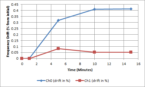
    Now, examining the data it looks like the CH0 sensor is drifting about 700Hz and CH1 is drifting about 100Hz. 

    Given that the data convers to the following frequencies: Ch0=0.173MHz and CH1= 0.196MHz, we can convert this plot to % frequency shift.

    We can see that the drift is on the order of 0.5% which means you could be seeing as little as 0.2pF parasitic shift in the sensor capacitance which sounds like it could be the culprit here. Note that some other sources of parasitic capacitance can come from the wiring that connects the inductor to the LDC pins and windings of the inductor itself which creates inner winding capacitance.

    I would first recommend to confirm your sensor parameters, including the dividers to eliminate the discrepancy between the calculated frequency and the measured. Then you could try to increase the sensor capacitor to help mitigate parasitic effects. 

    Regards,

    Luke LaPointe

  • hello,
    If it is for this reason caused by the small drift, how should I solve this problem?The project has higher requirements for accuracy.
    Thank you.
  • hello Luke :
    How to calculate the frequency parameters, and Can you recommend a divider parameters for us?
    If we increase the capacitance value, our oscillation frequency will be lower, it will work on the edge of the device parameters, may affect the use effect. If increase the capacitance value, whether our inductance value corresponding to reduce?
    Thank you.
  • Hello,
    In the example I gave above you can simply change your 22pF capacitor to a 100pF capacitor for improved performance. You can calculate the new frequency by using equation 9 in the LDC1612 datasheet (pg 37). Both a simplified formula as well as the full formula are given. The result you get here should match what you see from the device readings. Note that I would recommend starting with all of your divider settings set to 1 (CHx_FIN_DIVIDER = 0x01, CHx_FREF_DIVIDER = 0x001).
    Regards,
    Luke
  • hello Luke:
    Thank you for your advice,I will try to solve this problem as your suggest.
    Thanks.
  • hello Luke:
    I'm sorry to say that there are other questions to ask you. After increasing the capacitance, this also with frequency change.Can provide a suggestion for frequency range?
    What is the effect of RCOUNT_CH0 and SETTLECOUNT_CH0 register Settings for measurement?My Settings are as follows:
    LDC1612_write(0x08,0xffff); // write RCOUNT_CH0
    LDC1612_write(0x09,0xffff); //write RCOUNT_CH1
    LDC1612_write(0x10,0x0400); // write SETTLECOUNT_CH0
    LDC1612_write(0x11,0x0400); // write SETTLECOUNT_CH1
    Thanks.
  • Hello,

    The sensor frequency is determined by both the inductance value of your circuit and capacitance (whatever capacitor value you're connecting). You can then compute the sensor frequency as I mentioned above using equation 9 in the LDC1612 datasheet.

    For example, if you have L = 386µH, C = 22pF, then we expect the sensor to oscillate around 1.7MHz.

    To convert this frequency to what the LDC1612 DATA reads you can use equation 8 from the LDC1612 datasheet:

    Notice that this is also a function of the divider settings and the reference clock. For example, assuming CLKIN = 40MHz, CHx_FIN_DIVIDER = 0x01, CHx_FREF_DIVIDER = 0x001, We would expect the LDC to read 11408507 in decimal or equivalently AE147A in hex. 

    The other parameters you mentioned such as RCOUNT or SETTLECOUNT don't have an impact on this calculation, they merely effect the conversion time and the sample-to-sample noise in the data reading. A higher RCOUNT value yields a slower but less noisy measurement.

    Regards,

    Luke LaPointe