This thread has been locked.

If you have a related question, please click the "Ask a related question" button in the top right corner. The newly created question will be automatically linked to this question.

LDC1612: About target speed effect on LDC measurement.

Part Number: LDC1612
Other Parts Discussed in Thread: LDC1101, LDC0851, LDC1312, LDC1314, LDC1614

Hi,

I'm working on a project where the target is no fixed in front of the coil (thinking to a distance measure).
You can think to a disc rotating to a certain speed and the LDC1612 is used to measure the distance of this disc from the coil.
Suppose the distance is really costant but the speed of the target is not and not necessarly costant.
At the moment I have no way to test this, I'm just starting.
So the question is if there is a known effect of the target motion on the measurement.
Thanks

  • Hello Lorenzo,

    If you have a metal target that is rotating a fixed distance from your PCB then you can use an LDC device such as the LDC1612 (slower speeds) or LDC1101 (fastest speeds) to detect the speed.

    I would take a look at the following TI Designs which outline the basic principles of a speed based LDC sensor:

    Regards,

    Luke LaPointe

  • Thank you for your response Luke,
    My question arises from the concern that the measure produced by LDC can be affected by the speed.

    This should provide a clearer picture of the problem:

    The final project is to measure the diameter of the disk by evaluating the position of the external edge. The center is known...
    I think to use a square coil (stretched coil? ... differential coils?). Precision required is 0,1mm so I need to take care about several issues.
    - first thing is that the disk can be rotating
    - second is that the disk can be hot (not sure how much hot at the moment)
    - third coil-target distance probably not really constant
    and so on...
    I need to figure out how to compensate for all "interference" to achieve the desired accuracy.

    I just started studying it.These are the main problems I have identified, every suggestion is well accepted.

    Regards,

    Lorenzo

  • Hello Lorenzo,

    Thank you for clarifying your post. It sounds like you are trying to detect the diameter of your disc with the LDC device with 0.1mm of accuracy. This application is similar to what we call linear position sensing where you can either shape the coil or the target to get a linear response. Refer to the following technical documents for more information:

    Application Notes:

    Blogs:

    Articles:

    Let me comment on your other concerns below:

    Lorenzo Arosio said:
    - first thing is that the disk can be rotating

    The LDC devices operate on the principle of inducing eddy currents on conductive surfaces which is a very fast effect. There is a lot of information on the web that shows the transient effects of eddy currents on moving conductive surfaces which are able to form and reach steady state even on very fast moving surfaces. For example, see the following IEEE paper: http://ieeexplore.ieee.org/stamp/stamp.jsp?arnumber=497348&tag=1 

    Lorenzo Arosio said:
    - second is that the disk can be hot (not sure how much hot at the moment)

    Increasing the temperature of the disk will have an effect on the conductivity / resistivity of the material. At lower sensor frequencies this may manifest as a smaller target-to-sensor interaction and produce less frequency shift. This has to do mostly with the skin effect and we've outlined more information in the following application note:

    You may also consider the impact of thermal expansion of the metal surface getting slightly closer to the sensor or warping the metal surface to create a tilt or wobble. If this is the case then you may see an increase/decrease in response that is periodic with the rotation. 

    Lorenzo Arosio said:
    - third coil-target distance probably not really constant

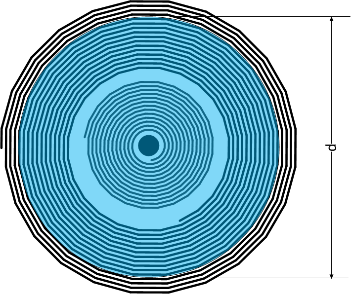
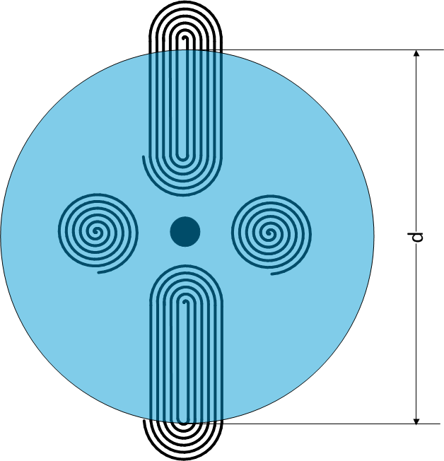
    Again if this is referring to a vibration or tilt of your disk as it rotates then it will show up as a repeated signal that rides ontop of the true signal which will show up as the common mode or true nominal frequency. If instead this is referring to a static difference in z-axis height between the target and sensor then you can simply add an additional sensor closer to the center of the disk such that even for the smallest disk diameter it sees 100% coverage. This will allow you to take the diameter of the disk out of the equation and you should have a proximity sensor that can approximate the z-axis height of your system and be used to compensate your disk diameter measurements. Here are some examples below that may work:

    Concentric spirals:

    Adjacent spirals:

    I would recommend that to address other concerns that you may have is for you to build up a prototype with one of our multi-channel devices like the LDC1314 or LDC1614 and add a few sensors in your system to calculate both diameter as well as z-axis height.

    Regards,

    Luke LaPointe 

  • Thanks for your suggestions Luke,
    you confirm a good part of my hypothesis and give me interesting ideas to think about.

    Surely we will make a prototype, but I need to understand how to make it ...

    Probably I will not be able to position the coils all around, as in your sketch ...
    but I can find the way to use more than one to improve the result. Surely I will have to get a distance measure.

    Thank you very much.

    Lorenzo