This thread has been locked.

If you have a related question, please click the "Ask a related question" button in the top right corner. The newly created question will be automatically linked to this question.

Linux/OPT3001EVM: IPGUI - Hardware not connected

Part Number: OPT3001EVM
Other Parts Discussed in Thread: OPT3001, , IPG-UI

Tool/software: Linux

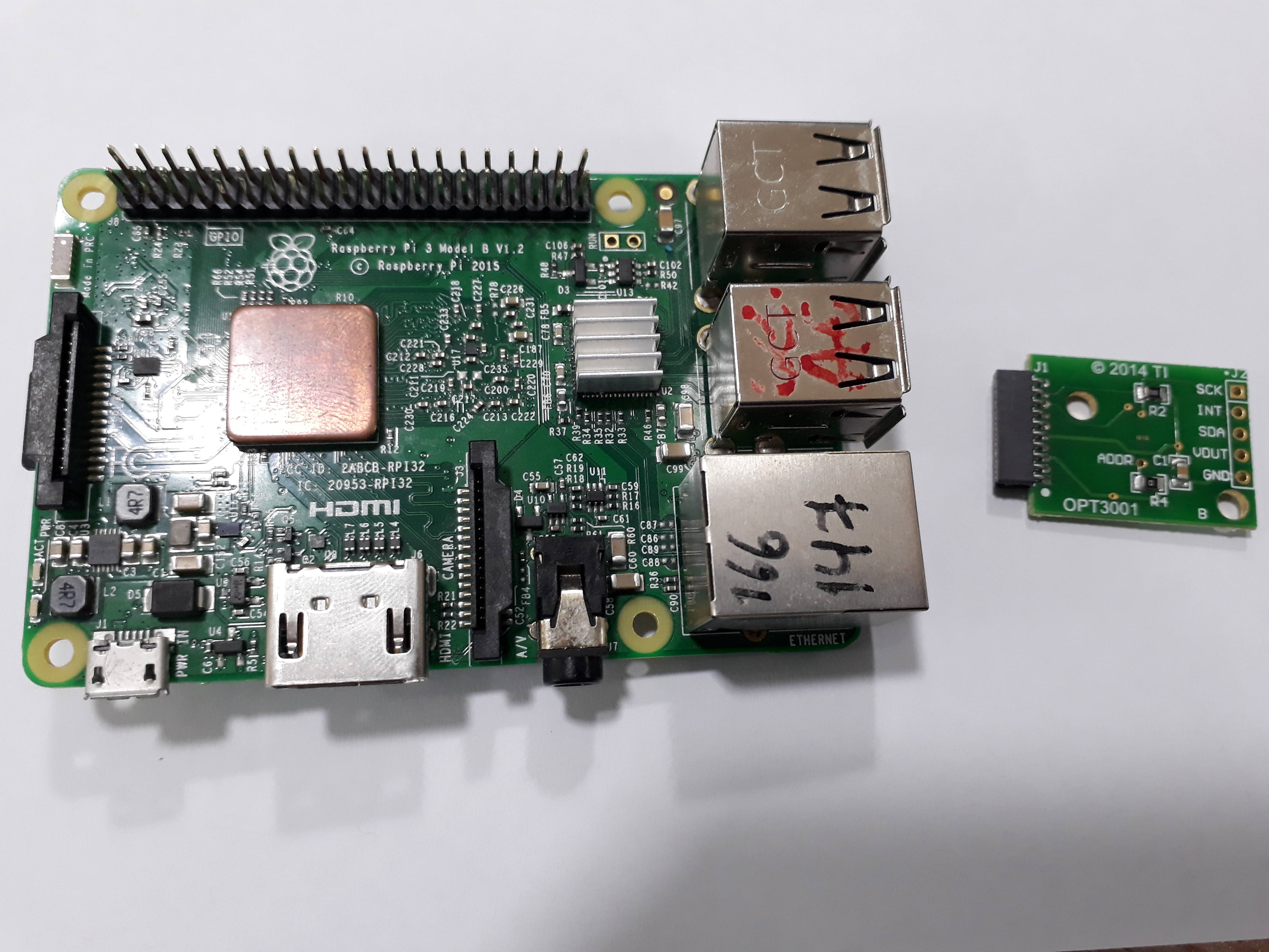
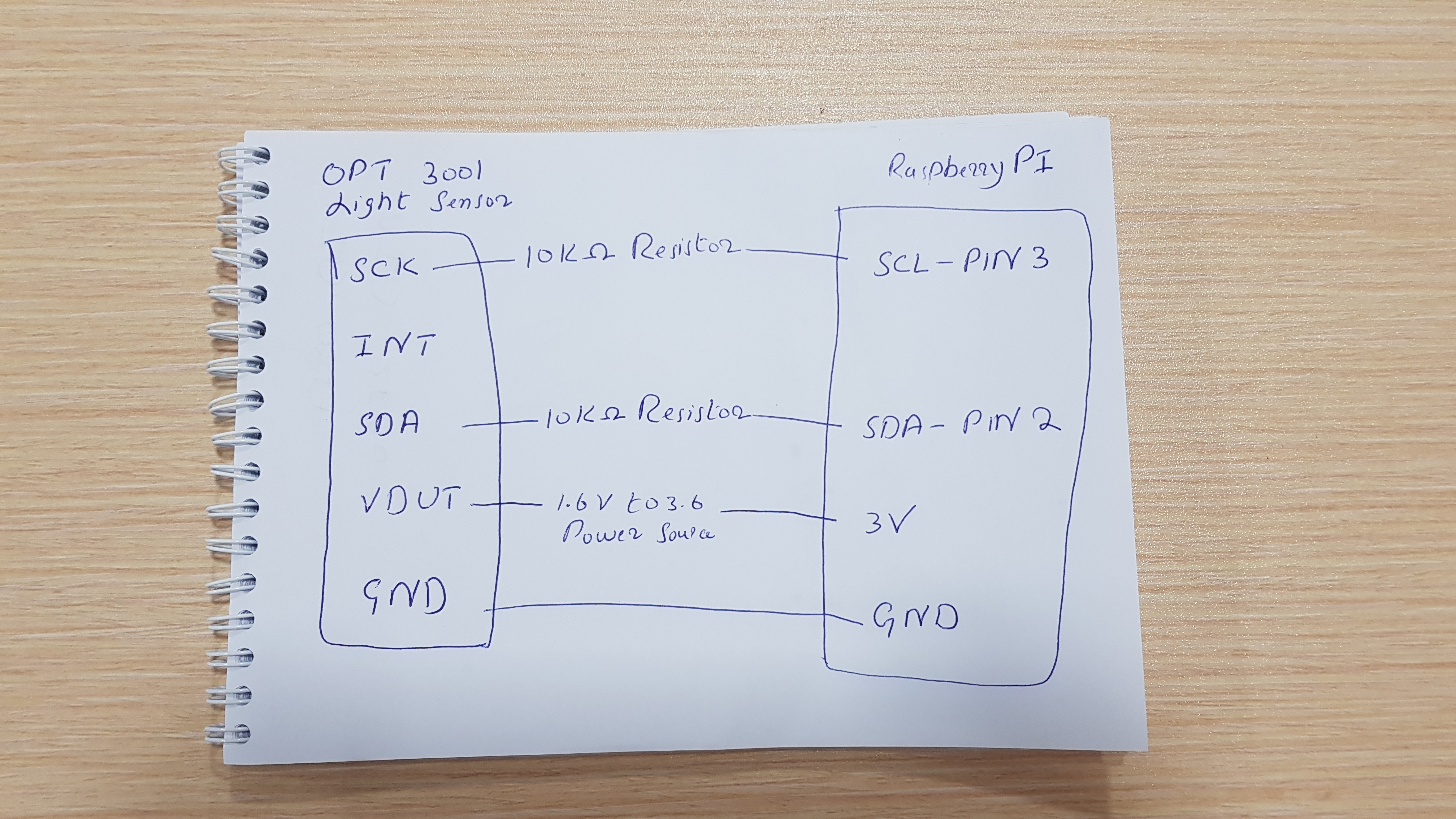
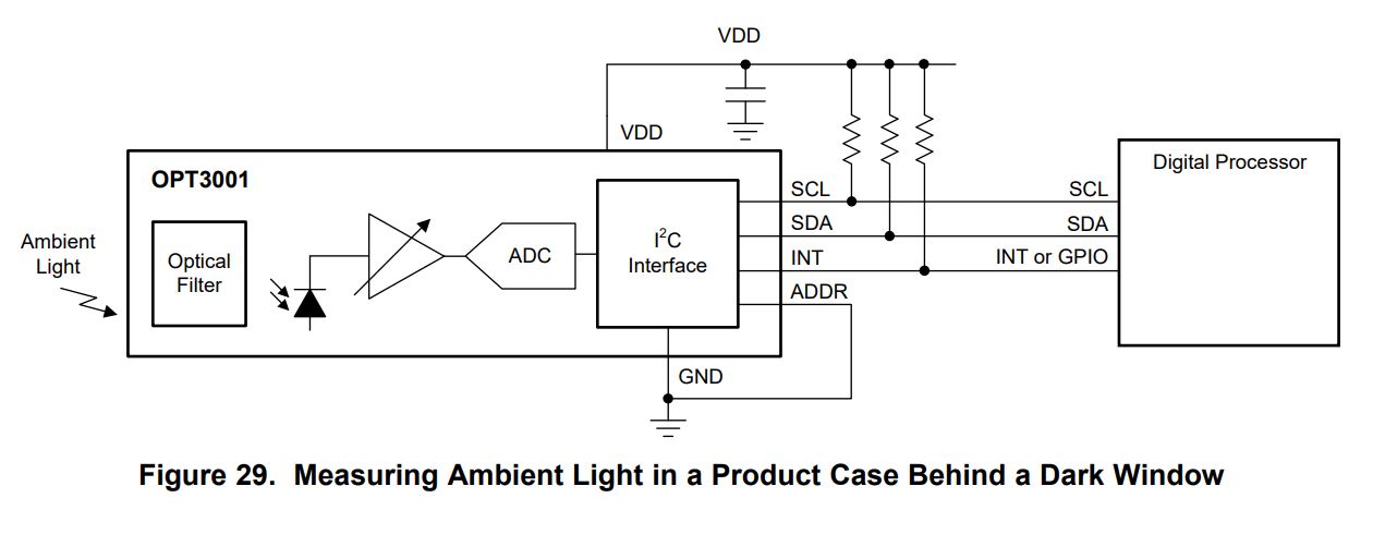
Recently, we have purchased OPT3001 to measure light intensity.

Please respond on below queries
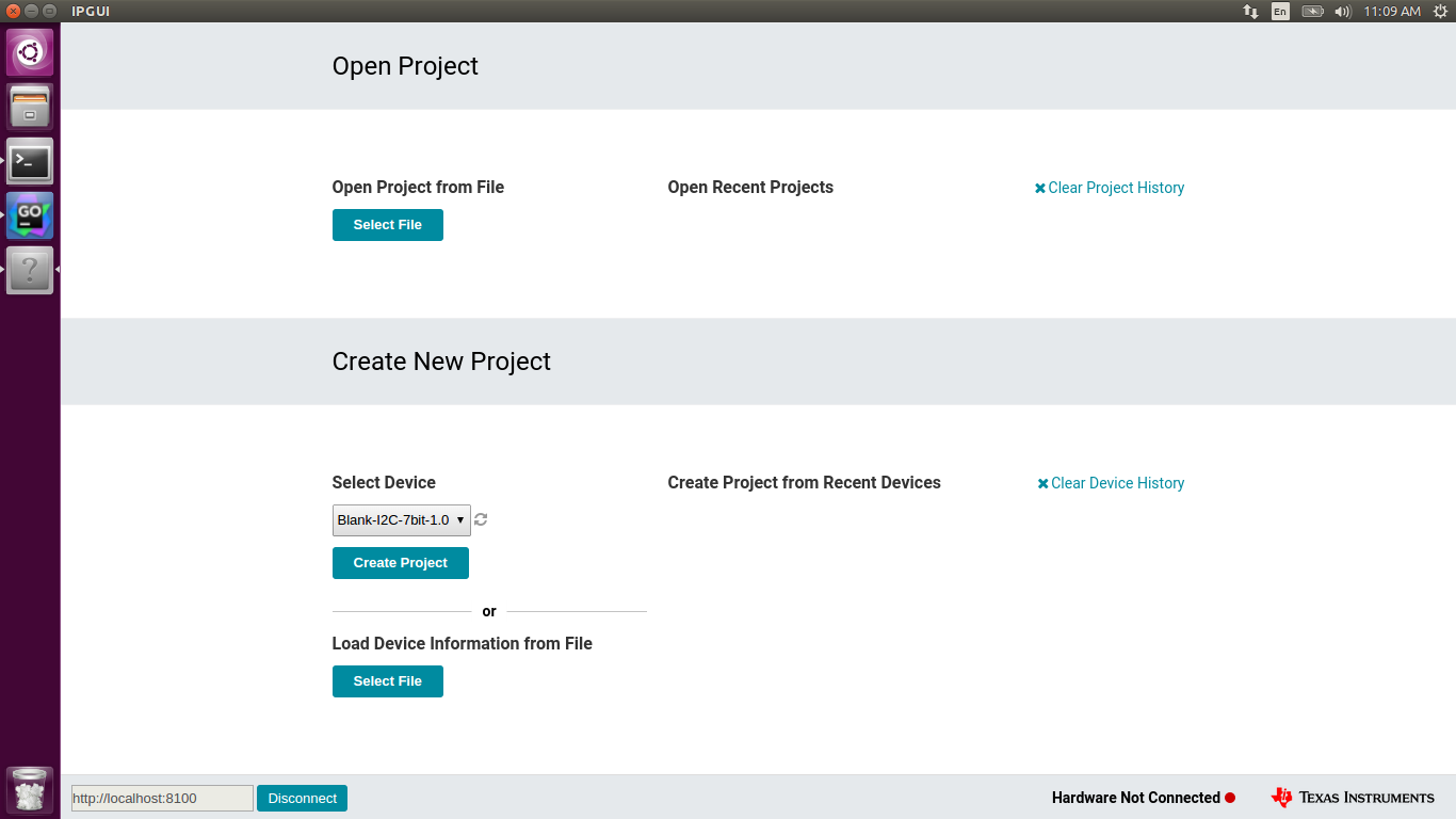
1) After installing IPGUI, it is showing Hardware Not Connected. Please advise how to fix it. 
2) Kindly provide sample in Golang to get  light intensity values from OPT3001 

Please note that we are using Virtual Machine Ubuntu 16.04. 

Regards,

  • Hello Akhter,

    Welcome to TI E2E forum!
    We have received your inquiry about operating the OPT3001EVM in linux environment and will get back to you by next week.
  • Hello Praveen,
    Kindly expedite and try to respond us this week.

    Best Regards,
    Minhaj Akhter
  • Akhter,

    As far as I can tell, the OPT3001EVM is not designed to operate with IPG-UI.
    Please download the OPT3001EVM GUI from www.ti.com
    Here is the link for your reference: www.ti.com/.../sboc443
    Please note that the EVM GUI (above link) has been tested on the Windows OS and not on Linux.

    You may find the Linux driver for OPT3001 here.
    www.ti.com/.../OPT3001SW-LINUX
  • Dear Praveen,
    We are still not able to run OPT3001EVM on Ubuntu & RaspberryPi.
    To add OPT3001 driver, do we need to recompile Ubuntu & RaspberryPi Kernels. In this regards, please advice.
    In addition, do you have any source code for Linux that is reading light intensity values from OPT3001.
    Waiting for your response.

    Best Regards,
    Akhter Ahmed
  • Dear Praveen,
    After using below commands opt3001 added to Ubuntu Kernel
    sudo apt-get install --install-recommends linux-generic-hwe-16.04 (Update Kernel)
    mkdir opt3001 && cd opt3001
    wget git.kernel.org/.../opt3001.c
    echo 'obj-$(CONFIG_OPT3001) += opt3001.o' > Makefile
    make -C /lib/modules/$(uname -r)/build M=$(pwd) modules
    sudo modprobe --all opt3001

    Please share some sample code for linux to check opt3001 is working fine with Ubuntu. In this regards, waiting for your response.

    Regards,
  • Dear Paraveen,
    Refer to above posts, Linux Driver for OPT3001 support I2C communication but we are using OPT3001-EMV with USB Interface.
    OPT3001 light sensor is connected with SM-USB-DIG board and SM-USB-DIG board is connected with Host PC through USB Cable.
    When we are connecting OPT3001-EMV light Sensor with USB interface, we are getting 2 address [0x01(1,OUT) 0x81(1,IN)]... 0x01 address used to write commands & 0x81 address is used to read commands through USB Interface.
    Kindly tell which commands I need to write to Sensor, so it can give us lux values.
    In this regards, waiting for your response.

    Best Regards,
  • Dear Praveen,
    Waiting for your response. Please expedite

    Regards,
    Minhaj Akhter
  • Hi Akhter,

    Thank you for your patience on this. It seems to me that there are two options to get this to work on Linux, but you will either need a Linux supported i2c interface or Labview for Linux.

    1) If you have access to an I2C interface the easiest route would be to use the Linux driver with a supported I2C interface and the OPT3001 (no SM-USB-DIG board).
    2) The OPT3001-EVM software is designed in Labview and compiled for Windows. However, we provide the source code on the EVM page http://www.ti.com/lit/zip/sboc450 If you have access to Labview on Linux you may be able to run the GUI on Linux. However, as Praveen noted, we have not done any testing on Linux and cannot guarantee that this will work.

    Are you simply trying to evaluate the OPT3001 or does your system involve running OPT3001 with a Linux device?

    Best,

    Alex

  • Dear Alex,

    We are developing a system that will run involving OPT3001. One of our target device is RaspberryPi 3.

    Please respond on below queries

    1. Which GPIO pin's from RaspberryPi will be connected with OPT3001 and to which pin's on OPT3001.

    2. How to construct a cable to interface OPT3001 & RaspberryPi. Please provide cable specification.

    3. Please advise do we need to add any driver for Jessie 8.0

    4. Please share some sample code.

    Immediate response is highly appreciated.

    Best Regards,
    Akhter Ahmed  


  • Hi Akhter,

    Please see my answers to your questions below

    1. You need to connect all the pins on the OPT3001. I2C has two pins, SDA and SCK, these will need to be wired to the I2C pins on the raspberry pi. The interrupt pin can be wired to a GPIO and should have a pull-up resistor. You will need pullup resistors in the i2c lines as well. Power and GND just need to be wired to an appropriate power source within the OPT3001 device specs.

    2. Standard cabling adhering to the i2c spec and power requirements should work. Are you planning on using the EVM breakout board in production?

    3. We have not tested on Debian jessie, but I think you should be good with the OPT3001 linux driver. It looks like some extra steps may be required for configuring I2C. I found this from a Google search so I am not sure if it applies to Debian but it might point you in the right direction: learn.adafruit.com/.../configuring-i2c

    4. The contents of the driver page is all of the sample code that we currently have for Linux at the moment.

    Best,

    Alex

  • Additionally, this link has some details on which raspberry pi pins to use for I2C learn.sparkfun.com/.../raspberry-pi-spi-and-i2c-tutorial

    Best,

    Alex

  • Dear Alex,

    Thanks for your prompt response. Please reply pn below queries

    1) Please find the attached image herewith & confirm that i2C cable specifications are correct.

    2) Please advise the commands through which we can read lux values from OPT3001.

    Best Regards,

    Akhter Ahmed

  • Hi Akhter,

    1. The 10k resistors on your diagram are pull-up resistors, correct? You may have meant this, but just to make sure, they should not be placed between the 2 devices but rather between the wire and Vdd power supply. Please see learn.sparkfun.com/.../pull-up-resistors for a nice diagram of this.

        The interrupt pin can be left floating if unused, but per the datasheet you will also need a pullup there if INT is used.

    2. For reading from the device please refer to registers 0x00 and 0x01 in the datasheet. The reading is read from register 0x00, but on power up the device will first need to be taken out of shutdown mode by writing to the config register (0x01). Please refer to the register map section of the datasheet (registers 00 and 01) for more details.

    Best,

    Alex

  • Dear Alex,
    Refer to above post, I am a bit confused. Please clarify on below queries.

    1) We should place pull-up resistor between OPT3001 SCK and SCL RaspberryPi? Please confirm

    2) We should place pull-up resistor between OPT3001 SDA and SDA RaspberryPi? Please confirm

    3) We should not place pull-up resistor between Vdd power supply ? Please confirm

    Its better if you share a cable configuration diagram, this will ease our task.

    Waiting for your response.

    Best Regards,
  • Dear Alex,
    Waiting for your response.

    Regards,
  • Hi Akhter,

    Please refer to figure 29 of the datasheet (pasted below). It provides a nice illustration of this.

    Best,

    Alex

  • Dear Alex,
    We build the cable & able to deduct the OPT3001 on RaspnerryPi. OPT3001 Address is 0x44.
    When we are sending command(C8h,10h) to register 01h, it respond us (C8 10 FF FF FF FF FF FF FF FF).
    After that we start reading register 00h and it respond us (0 0 FF FF FF FF FF FF FF FF).
    Please advise what is wrong in our commands and why OPT3001 does not respond with lux values.
    In this regards, waiting for your response.

    Best Regards,

  • Hi Akhter,

    C810h is the default value of the config register (01h) and keeps the device in shutdown mode. You will need to bring the device out of shutdown. The lux readings can then be read from the result register (00h). Please refer to the datasheet for details on the config register. Specifically you will want to check bits 9 and 10 (Mode of conversion operation field) of the config register to choose the conversion mode you want to use.

    Best,

    Alex