


Hello;
Few months ago we bought a TDC1000 Ultrasonic Sensing. The datasheet says that transmitter channels TX1/TX2 supports programmable excitation in range 31.25 kHz to 4 MHz. According with the last, we use a 4MHz piezzoelectric ceramic as transducer and clock input of 8MHz. Using a oscilloscope we checked that the signal generated and the echo receive was right (attached figure 1). But, when we tried to use the LNA and PGA (we activated it changing the register, of course ), the signal was not amplified, even we got more noise. We tried several arrangement, we changed the filters between LNAOUT and PGAIN, we changed the filters between PGAOUT and COMPIN, among the others configuration of the TDC1000 and we did not see any change.
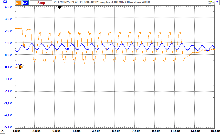
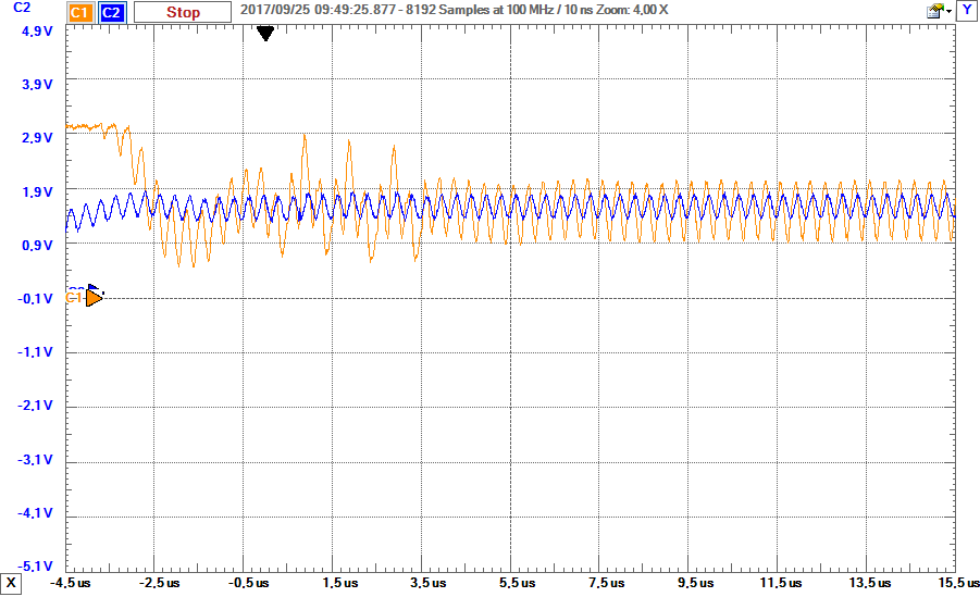
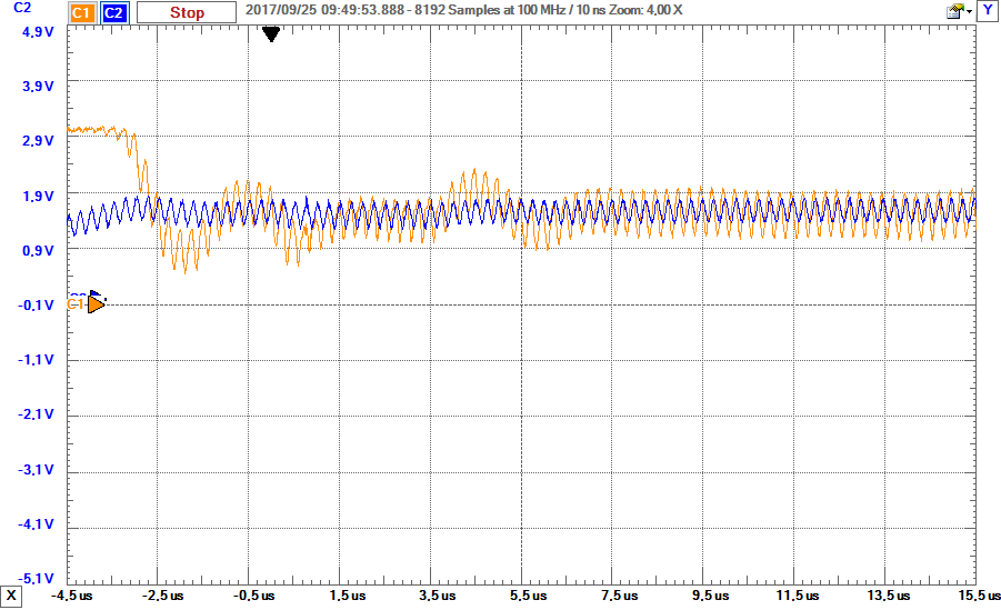
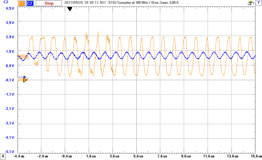
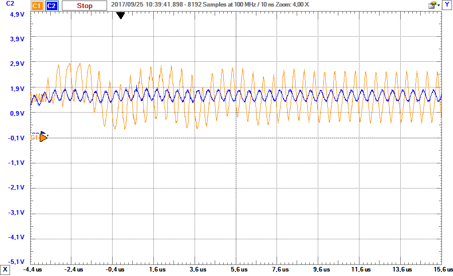
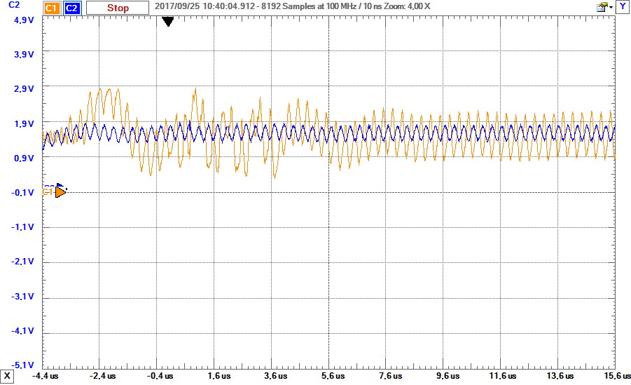
Finally, we tested the filters each separately. First, we activated the LNA (capacitive feedback, C =165pF and C = 300pF), bypassed the PGA and deactived also. Then, we generated a input low signal of 1, 1.5, 2, 3 and 4MHz at the receive pin RX1. We noticed that the amplifier of low noise work fine for frequencies below 2MHz and for frequencies above 2MHz, it does not amplify and the signal is deformed. (see attached figures LNA_1MHz, LNA_2MHz,LNA_3MHz,LNA_4MHz).
Also we tried the PGA filter, we bypassed the LNA and repeated the process. We got the same results (see attached figures PGA_3dB_XMHz ) for diferents values of dB.
In conclution, we think that the TDC1000 does not work for 31.25kHz-4MHz, because the amplifiers incorporated does not work in this bandwidth, despite what the datasheet says in section 6.8 Typical Characteristics.
thanks for your help
Figure 1:

LNA 1MHz
LNA 2MHz

LNA 3MHz
LNA 4MHz
PGA_3dB_1MHz
PGA_3dB_2MHz
PGA_3dB_3MHz
PGA_3dB_4MHz

