Because of the holidays, TI E2E™ design support forum responses will be delayed from Dec. 25 through Jan. 2. Thank you for your patience.

This thread has been locked.

If you have a related question, please click the "Ask a related question" button in the top right corner. The newly created question will be automatically linked to this question.

LDC1614EVM: Inductance of the coil

Part Number: LDC1614EVM
Other Parts Discussed in Thread: LDC1614

Hi,

I am using LDC1614 EVM and  Q coil (Dia = 6mm) from LDCCOIL EVM for analysis. The inductance and frequency values which I am seeing in GUI are not matching with theoretical values. The below pictures shows calculated values and the real inductance and frequency values getting in GUI. I am using 560nH series inductor and 220pF capacitor on 6mm coil.

Calculated values                                                             

L with no target = 3.957uH                                               

Frequency = 5.339Mhz

GUI values

L with no target = 5.2989uH              excluding series inductance                        

Frequency = 4.433Mhz

I have attached picture of setup

Please help me to find the reason why theoretical values are not matching with GUI values.

  • Hello Tousseef,

    The excel calculator tool provides a conservative estimate of the sensor inductance, and also uses a simple process to estimate the target interaction - the conductivity of the metal and skin depth effects are not included. Also, parasitic inductances and capacitances are not included in the calculations. Usually, the calculator is within 10% of the true inductance in free-space, but the target interaction uses a curve-fit which doesn't include things like proximity effect and so on.

    Regards,

    ChrisO
  • Hi Chris,

    Thank you for valuable response.

    In this case conductivity of the metal and skin depth should not change the inductance and frequency values because I am not using any target (metal). The values which I have shown here are without any target interaction (as shown in setup). I agree that parasitic inductances and capacitances are not included in the calculation but does these parameters alters the values by more than 35% of the true inductance?

    Is there any document which can guide me to choose the series inductance value for tiny coil?

    Regards,

    Tousseef

  • Hi Tousseef,

    What is the tolerance of the fixed inductor? Did you measure it before inserting into the system?

    We recommend using a shielded inductor for the fixed inductor.

    In addition, did you adjust the Glitch Filter setting in the GUI - the nominal setting is 3.3MHz; for your sensor you should set it to 10MHz.

    Regards,

    ChrisO
  • Hi Chris,

    Tolerance of the inductor is 2%. Inductor used for testing is 1206CS-561XGLB. I didn't measure the inductance but I tried with multiple inductors of same value still I am getting the same inductance and frequency values in GUI. Glitch filter setting had set to 33MHz and tried changing it to 10MHz but there is no change in the  L and freq values.

  • Hi Tousseef,

    Have you tried probing the INx pins to measure the sensor frequency? This will provide us a better insight into where the error in the inductance calculation might be creeping in from?

    And just as an FYI Coil Q from the reference board has a nominal inductance of around 4.8 uH. The measurements have been provided in the LDC Reference Coils User Guide.

    Which puts us really close to the value the GUI is showing.

    Regards,

    Varn,

  • Hi Varn,

    Frequency on the INx pin is exactly equal to the GUI frequency. It is 4.4MHz and amplitude is 1.64V. As you told the inductance of the coil Q is close to the value in GUI , is anything wrong in the calculation?

    I hope it will not affect the performance of the LDC. One more query,

    What should be the minimum change in inductance due to the target interaction to avoid false detection ?

    In our application the change in inductance due to target interaction is 0.070uH . I guess it is very less. If so what should the minimum change?

  • Hi Tousseef,

    The inductance change seen as a conductive target comes closer to the sensor is a factor of the sensor size, target size, target conductivity, and target distance (distance between sensor and target). You get the best sensitivity when the target distance is less than half the sensor coil diameter.

    So to improve sensitivity you can either use a bigger coil (I am assuming the target is larger than the sensor?) or move the target closer to the sensor. Is the target copper or aluminum? Targets with higher conductivity will provide a better response.

    As far as your setup is concerned, I would look at the raw output code from the LDC device and look at the code jump as the target moves into the detection range. If the code jump you observe is larger than the noise floor ( 6*std dev) then you are probably okay.
    At 0.07 uH inductance shift you are still well above 10,000 PPM in inductance changes which is well within the measurement capabilities of the LDC devices.

    Regards,

    Varn.
  • Hi Tousseef,

    It also looks like your inductor may not be shielded; it is possible that the higher inductance you are seeing is due to coupling between the sensor and the fixed inductor.

    Regards,

    ChrisO
  • Hi Varn,

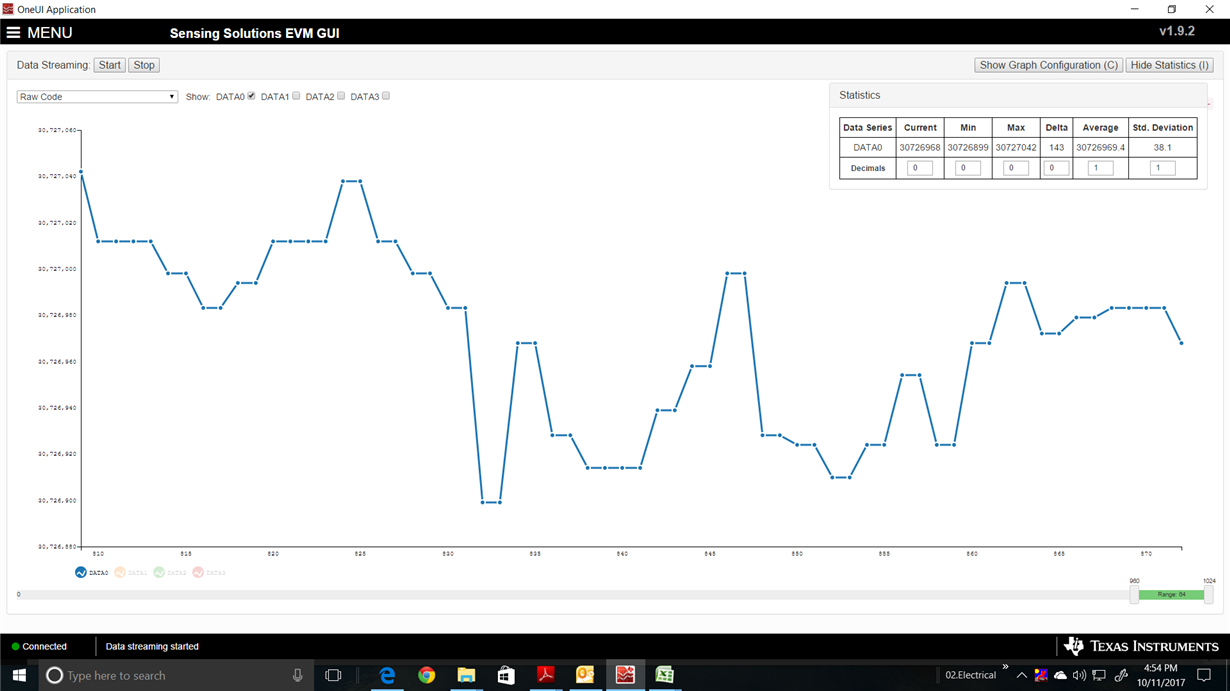
    Target used is rectangular steel dome of size 5.59mm x 4.19mm and the coil diameter is 6mm. Target is very closer to the sensor. We are using a thin (0.2mm) plastic sheet in between metal and coil. Dome can make a movement of 0.30mm. Picture shows here the raw code without switch press and with press.

  • First capture is for when pressing the switch and the other is for no press
  • Hi Chris,

    Yes , series inductor might be the reason. I will test with shielded inductor once I get it and I will share the results.

    Thanks,
    Tousseef
  • Hi Varn,

    Tried with multiple metal domes differing in diameter. With all the metal domes code jump is less than 6*std dev. Please find the below results.

    Ls=1uH,C=220pF, Coil=6mm
    Metal dome Change in code Std dev Noise (6*std dev)
    1 603667 219181 1315086
    2 911173 359367 2156202
    3 274870 115675 694050
    4 180244 67748 406488
    5 496400 193997 1163982
    6 233238 96222 577332
    7 434630 175895 1055370
    8 332598 127080 762480
    9 261697 101362 608172
    10 584425 216604 1299624
    11 1331569 508985 3053910

    If this doesn't work, how to reduce standard deviation ?

    Thanks,

    Tousseef

  • Hi Tousseef,

    Were these measurements done with a shielded inductor?


    Regards,

    Varn
  • Hi Varn,

    Yes, these measurements are done with a shielded inductor.