This thread has been locked.

If you have a related question, please click the "Ask a related question" button in the top right corner. The newly created question will be automatically linked to this question.

FDC2212: Speed, Resolution, Flat Response and Temperature Stability

Part Number: FDC2212
Other Parts Discussed in Thread: FDC2112
There are several aspects of the FDC2212 that I am struggling with:
  1. Poor resolution at high speed:
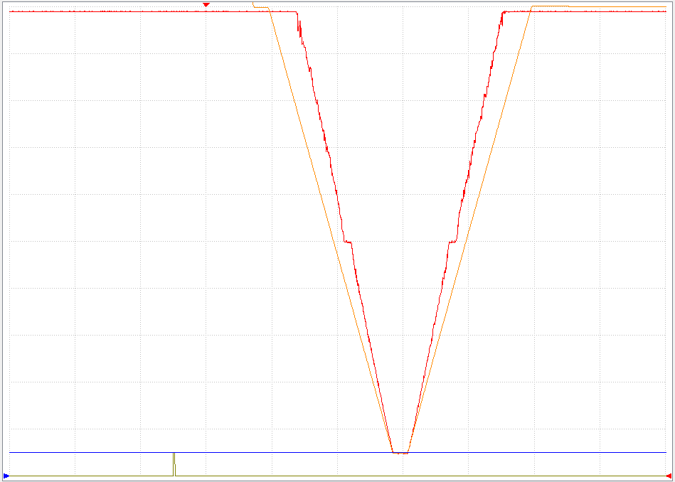
    I need my system to measure at least 1000 samples per second. With my physical sensor configuration my resolution at 5mm is about 0.2mm.
  2. Capacitive reading has some flat spots:
    As I increase the distance between my sensor and grounded plate, there are sections where the reading does not change at all. Changing the parameter for Drive Current seems to change where this happens so I can minimize the issue. Usually I end up with a setting of 11101 => 1.167mA. But variations from IC to IC seem to require changing this setting.
  3. Thermal stability is a serious issue:
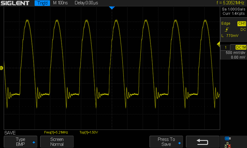
    I am using a 33pf C0G/NP0 capacitor in the tank circuit. I also picked a "High Thermal Stability" inductor. Wurth 10uH. 744758410A. 
To get the highest speed and resolution I am limited to a single channel. I am planning on monitoring the temperature with a thermistor and compensating for the thermal drift with a microcontroller. But I'll need to characterize each one by running through a thermal cycle. I'll also have to check for flat response and optimize the drive current. I'll use some averaging of several readings to increase my resolution but this also slows my sample rate.
 
Any suggestions?
Can I change the tank frequency to get more resolution? Can you recommend a better inductor for thermal stability? What is the cause of the flat areas where the reading doesn't change? Since I don't get very high resolution anyway, would I be better off with a FDC2112?


  • Hi Gerry,

    Can you provide a scope-shot of the sensor signal - perhaps the sensor signal is too low in amplitude? Also, please provide the exact output code that the flat spots are occurring at.

    You may be able to use a 2nd channel as a reference but sampling at a very low RCOUNT so that the reduction in your sample rate is minimal; you could then use a moving average of the RCOUNT on the second channel to compensate for the temperature.

    Regards,

    ChrisO
  • I'm trying to capture a good scope trace to show you the flat area. I'll post that when I get it.

    Currently my RCOUNT is set for 0x03FF. If I make it lower my resolution drops further. Here is an example of my raw FDC output number for CH0 with my sensor distance constant:

    35852119
    35852681
    35852681
    35852681
    35851023
    35852681
    35852681
    35852681
    35852681
    35851585
    35851585
    35851585
    35852147
    35851585
    35851585

    You can see that this set of numbers doesn't really have a continuous change, it changes in steps of about 540. If I decrease the sensor gap from 12mm to 10mm I get a change in the reading of about 1000 so this lack of resolution is significant. Also, at this RCOUNT setting and single channel mode sequencing my sample time is about 500usec. Not much time for me to do additional processing. Maybe I'm missing something, but if I switch to multi-channel sequencing I'll have an additional sensor activation and switch delay. If I lower my RCOUNT I'll loose even more resolution.

  • This might be a good clue for the flat sections. Attached is a graphic showing a linearized output of the FDC data that is run through a DAC (red line). The orange line represents the sensor gap (1mm/div).

    Eventually I was able to monitor the RAW FDC output and found that the number it was getting stuck at was 35791394 which turns out to be 0x2222222. There must be some significance there. At first I was wanting to blame my code, but on further inspection I believe this is real data coming from the FDC.

  • Hello Gerry,

    My apologies for the delay in response. What you are seeing is probably due to Injection locking; refer to section 2.5.2 of www.ti.com.cn/.../snoa944.pdf. The FDC221x can also experience this effect. Try increasing the sensor IDRIVE, improving the sensor Q, or shifting the sensor frequency to avoid the region.

    The internal oscillator is much less likely to cause this effect. If you cannot use the internal oscillator, try to reduce the voltage drive of the external oscillator signal; also try to avoid routing the oscillator too close to the sensor signals.

    Regards,

    ChrisO
  • Thanks for the reply Chris. I'll see if I can adjust my frequencies to avoid the injection locking but with the amount of temperature drift causes the sensor frequency to vary quite a wide range.

    Do you have any recommendations on speed and resolution?

    One thing that I was noticing on Friday was a significant amount of lag in the capacitive readings. Even though the output signal seems to be updated at a rate in 600usec range, there is a much more significant amount of lag. This is resulting in a hysteresis of my system. I'll see if I can capture the data graphically so you can get a better feel for what I'm seeing.

  • Hello Gerry,

    Are you using the EVM and the Sensing Solutions GUI? If so, then keep in mind there are limitations on the maximum throughput of the USB connection (it only uses USB1.1). You can make sure you are using the actual data output rate from the LDC by settings the graph configuration to use the EVM output rate (refer to section 2.8.5 of ). In addition, the GUI will occasionally present a significant amount of lag; this is something we are looking into and I can confirm that it is disruptive.

    However, if you are not using the GUI, then the device itself does not have any major source of lag beyond the configured sample rate latency.

    Regards,

    ChrisO

  • Hi Chris,

    I am not using the GUI. The FDC is being read by a micro and that reading is being converted into an analog signal through a DAC. Trying to quantify the lag is challenging because I have to capture the actual gap position and the FDC reading at the same time. I'm trying to minimize any lag that may be caused by my code or other aspects of my setup.

    I looked at my signal with a scope to find out what my signal voltage voltage is. With the drive current set at 1.167mA I get a peak voltage of 1.5V. The signal looks a little weird so I thought it was worth posting.

  • Hi Gerry,

    You shouldn't have ringing on the bottom half cycle of the waveform, although this could be due to your scope. Were you probing near the sensor or the device?

    As for lag or latency, there should be no lag beyond the configured conversion time.

    Regards,
    ChrisO