This thread has been locked.

If you have a related question, please click the "Ask a related question" button in the top right corner. The newly created question will be automatically linked to this question.

CCS/pga460: PGA460

Part Number: PGA460

Tool/software: Code Composer Studio

I need help on the PGA460
1. I will use uart asynchronously, only tx and rx
2. connect tx from pga460 to microcontroller rx, pga460 rx to microcontroller tx
questions
1. something must be done so that the PGA460 understands that the communication is by the serial port UART?

on page 45 (7.3.8.2 UART Interface), fig 36 of the manual, talks about placing a low in the uart for 300us, this is not very clear

I appreciate any help

  • Luis,

    To use the asynchronous UART mode, refer to the 7.5.1 UART and USART Communication Examples on page 55 of the PGA460-Q1 datasheet. Try replicating these commands using your master MCU. Be sure your master MCU is using the PGA460 required UART frame structure:
    8 data bits
    1 start bit
    2 stop bit
    No parity bit
    No flow control
    Interfield wait time (only required when using 1 stop bit)

    Ensure you have the latest revision of the datasheet (Rev.A). Page 45 of Rev.A does discuss 300us, but I assume you are refer to the wake-up high-to-low toggle time requirement when exiting low-power mode. This is not necessary for standard/initial operation, so ignore the 300us for the time being.

    Your hardware connections are correct: master MCU RX to PGA460 TX, and vice-versa.

    For additional async UART examples, refer to the GUI's Interface Mode --> UART page's command selection. Select the desired command from the drop-down with the appropriate UART Addr (0 by default), then click Run Command to see the raw serial sequence with appended checksum printed in Hex format on the UART terminal.
  • thanks to your help now is working well communication, I can read and write the records, in the other manual was the error, thanks for your clarification.

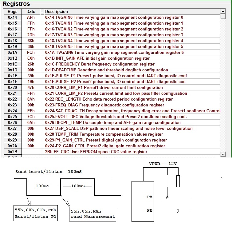
    now I have another problem I do not generate the pulses in PA and PB

    I put pull-up resistors to vpwr, in the outputs PA and PB (I do so to go step by step and commit the least errors)

    I follow the procedure, I set P1, P2, Freq, Lim1 and LIM2

    in the attachment are all records read directly from the PGA460, I also show the sequence that I am following after initializing the register,

    every 100mS I send first burst / listen (55h, 00h, 01h, feh), I wait 100ms and send measurement read command (55h, 05h, FAh), but on oscilloscope I always see the two PA and PB signals high (VPWR)

  • I ALREADY RESOLVED
    THE PROBLEM WAS FAIL TO INITIALIZE AT LEAST ONE OF THESHOLD
    THANKS EVERYONE FOR YOUR HELP