This thread has been locked.

If you have a related question, please click the "Ask a related question" button in the top right corner. The newly created question will be automatically linked to this question.

AWR1642BOOST: AWR1642BOOST is not connecting to COM port.

Part Number: AWR1642BOOST
Other Parts Discussed in Thread: AWR1642, , UNIFLASH, CC1310, CC3200

Hi All.

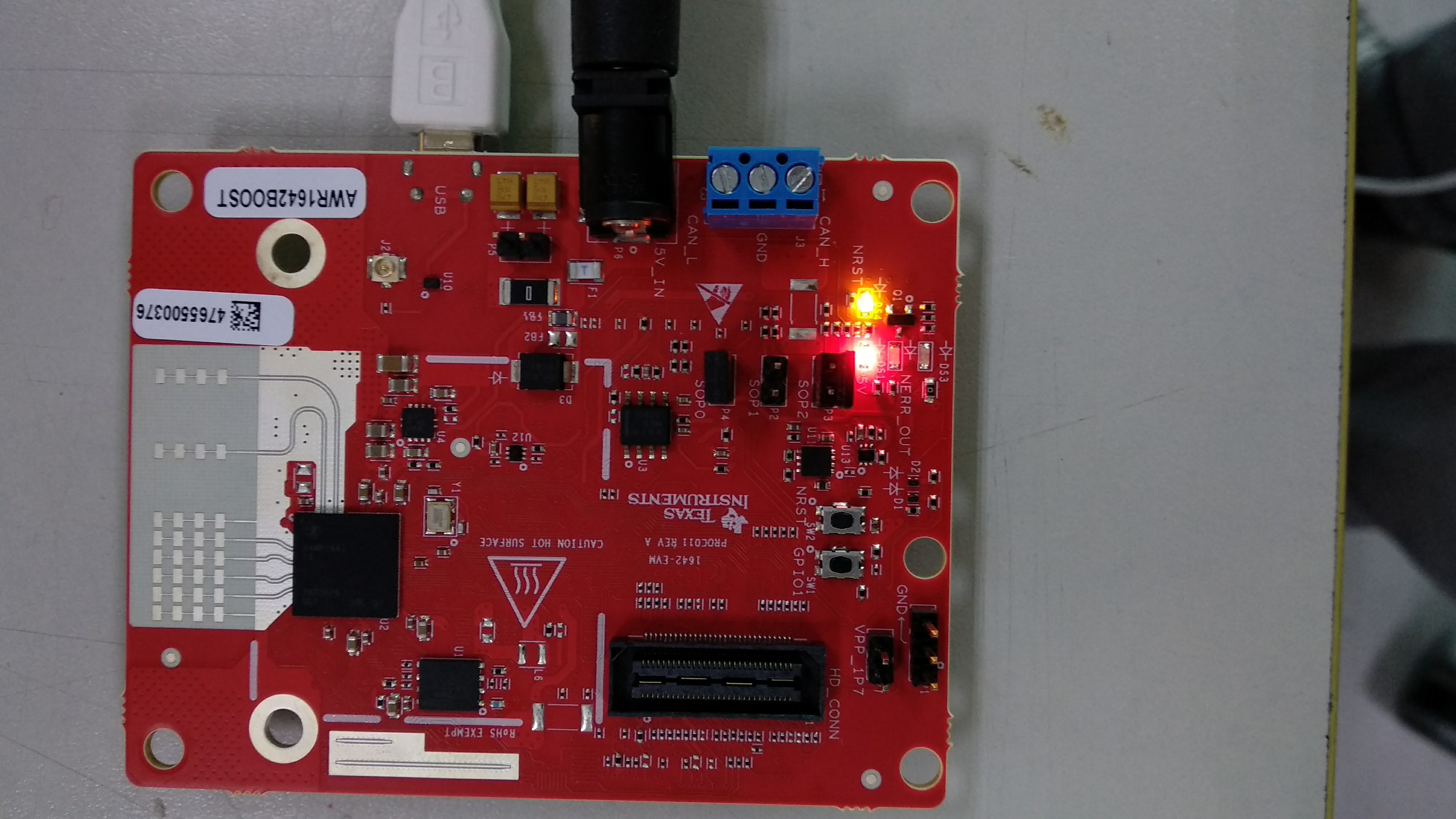
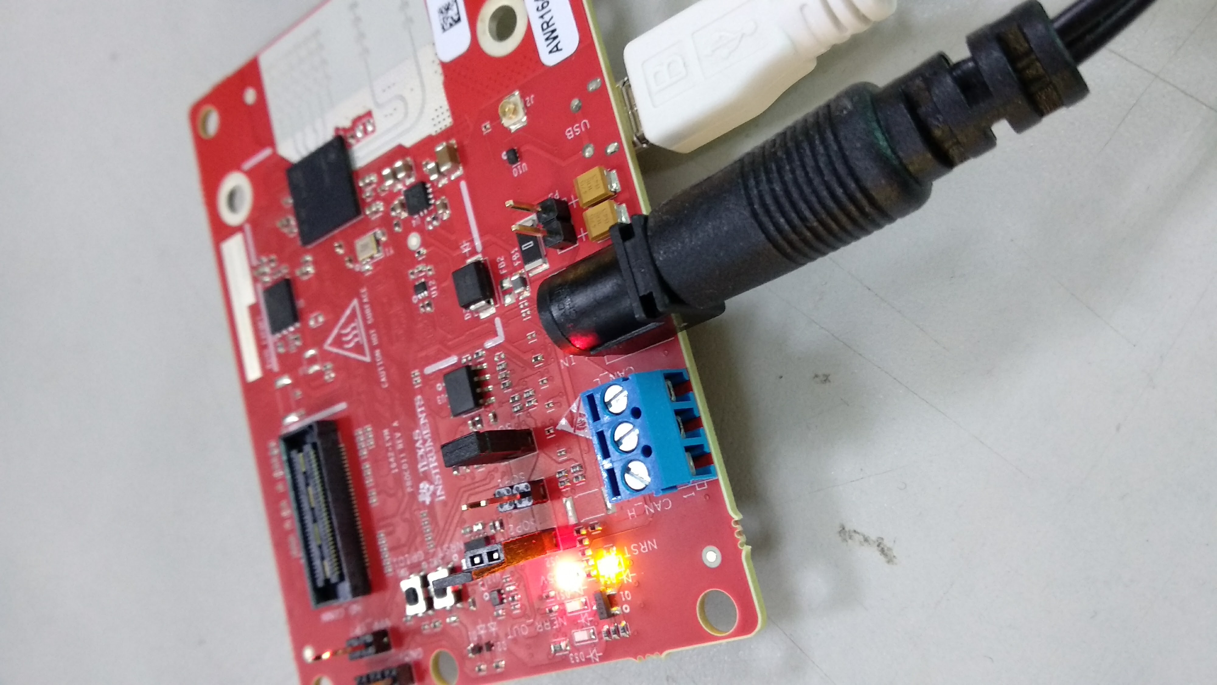
  I buy a AWR1642BOOST to start a project with this IC. When I going to test in mmWave Demo Visualizer always stays in "waiting for the data" for COM ports. I thought this happens beacuse the AWR1642 it didn't have the xwr16xx_mmw_demo.bin burned in the IC. The power supply have 5 Amperes in 5V for supply the AWR1642.

  When i try to burn the xwr16xx_mmw_demo.bin, the uniflash can't connect to AWR1642BOOST, but the uniflash detect a AWR1642BOOST connected to the system. I have the jumpers closed to SOP0 and SOP2 like says the manual to burn the firmware. But the uniflash give me to an error. It say it can't connect to COM port. I don't have any other program connect to the COM port. I have configured fine the SOP mode. I read all the threads that have the same problem and anything doesn't works with my problem.

  I test this in 4 PCs different, 3 With Windows 10 (1 with a fresh install) and other with Windows 7 with uniflash fresh install and all of them say the same thing. I test the boards with different power supplies and different cables MicroUSB and nothing.

  I attach the images of AWR1642BOOST connected and the software screenshoots and log. I need to make works the AWR1642 to start to develop my project.

08:32:19:798 log - NWAgentAPI: dinfraConfigue resolved successfully.
08:32:19:997 error - {}
08:32:41:554 debug - ufDS, session.configured, partnum of current session = awr1642
08:32:41:639 debug - addTargetStateListener on Cortex_R4_0
08:32:59:354 debug - returning new configure
08:33:02:800 debug - configured
08:33:03:895 debug - connect to core Cortex_R4_0
08:33:04:021 error - Image loading failed: Not able to connect to serial port. Recheck COM port selected and/or permissions.
08:33:18:036 debug - AddQuickSetting. id: Setup, type: category, core: Cortex_R4_0
08:33:18:884 debug - AddQuickSetting. id: Format, type: category, core: Cortex_R4_0
08:33:46:667 debug - returning cached configure
08:33:46:678 debug - connect to core Cortex_R4_0
08:34:06:862 error - Image loading failed: Not able to connect to serial port. Recheck COM port selected and/or permissions.
08:34:12:843 debug - SettingsButtonPressed. Call: performOperation, Action: Format
08:34:12:844 debug - returning cached configure
08:34:12:857 debug - connect to core Cortex_R4_0
08:34:33:102 error - Not able to connect to serial port. Recheck the COM port selected.
08:37:33:049 debug - session service: new()
08:37:33:051 debug - cores disconnected: {}
08:37:33:335 debug - deconfigured
08:37:34:257 error - {}
08:39:09:403 debug - Target Configuration. Device: awr1642, Connection: Serial_Connection, LP: true
08:39:09:519 debug - ufDS, session.configured, partnum of current session = awr1642
08:39:09:528 debug - addTargetStateListener on Cortex_R4_0
08:39:19:621 debug - AddQuickSetting. id: COMPort, type: property, core: Cortex_R4_0
08:39:22:152 debug - AddQuickSetting. id: DownloadFormat, type: property, core: Cortex_R4_0
08:40:00:973 debug - returning new configure
08:40:01:190 debug - configured
08:40:02:282 debug - connect to core Cortex_R4_0
08:40:22:592 error - Image loading failed: Not able to connect to serial port. Recheck COM port selected and/or permissions.

  Thanks in advance.

Best Regards.

  • Hello Fran Serrano,

    All the steps you mentioned seem to be right. Also the hw is setup right . Jumper settings seem right with SOP2 and SOP0 closed for flashing (Only issue could be only if the jumpers themselves are not right).

    There is a known issue in the Uniflash with "Detect My device feature" .
    Please select the device manually "Choose your device" option in the Uniflash.

    -Raghu
  • Hi Raghu.

      I choose my device manually, i Test the option with AWR1642 and AWR1642BOOST selecting by me, and no works. I don't know what more can i do??

      I change the jumpers and the behaviour is the same. I can't flash the AWR1642.

      I test in other two PCs, one with Windows 10 and other session with Xubuntu 16.04 LTS, and the other PC have Windows 10 and Ubuntu 16.04 LTS. The uniflash can't burn the firmware in any PC or any OS. I think is a hardware Issue, never have response from the AWR1642. How can I see if the IC is running?? or anything??. Please help, I am triying like a month and I can't make running the board.

    Best Regards.

  • HI again.

    I am traying to see if AWR is running, because I don't get response from the IC, but i don't know how i can see if the AWR1642 is running in any pin for example in connector of J5 o J6. In this Pin headers the 3,3v and 5V signals are given to me 0V, I don't know if it is normal. Can any one help me??. I don't know if the bootloader is not running well, because in any mode get any response.

    The things I thinks is the AWR not have a good bootloader or the Boost has any fail hardware PCB, if you want i can make a video to see if I do anything wrong, but I am working for years with ICs of texas instruments like CC3200 (Have SOP mode to load de firmware) or CC1310 etc.., because this, I think i am doing the steps to load de demo firmware correctly.

    Best Regards.
  • Hello Fran,
    Did you power cycle the EVM after changing the jumpers? ie remove the 5V supply from the AWR1642BOOST, put it back and then press the nRST switch (SW2) ?
    Incase that does not work we would need to check if the IC has got damaged by any chance. To check if the IC is powering up can you probe the voltage on the C56 decap? Once you provide the 5V supply this decap should have approximately 0.9V voltage if the device is powering up. Note that one side of the decap is GND, so you need to probe the other side connected to the VBGAP signal. You can refer to the schematic pdf and the assembly pdf of the EVM to location of this decap on the PCB (www.ti.com/.../sprr251).

    Regards,
    Vivek
  • Hello Vivek.

      In C56 has 0.82 more or less, I attach to you a screenshoot from oscilloscoper, and I attach too a video that I show how I try to load the firmware. I test power cycle before jumpers, after changing jumper all the things I can think to do, I try it on 6 PC differents, in differents SO (Windows 7, Windows 10, Ubuntu 16.04 LTS, Xubuntu 16.04 LTS). I don't know what more can I do.

      Link to video: https://photos.app.goo.gl/uu0BKv6PU8OQyxtq1

    Oscilloscoper.

    Best Regards.

  • Hello Fran,
    Thank you so much for capturing these details. The device seems to be working since you are able to see 0.82V.
    Just to make sure there is no assembly issue can you check if R128 and R129 are present on your board?

    Regards,
    Vivek
  • Hello Fran,
    If the resisters are mounted then can you try to JTAG connection via CCS in the functional SOP mode (mode 4) ?


    Regards,
    Vivek
  • Hello Vivek.

    The R128 and R129 are mounted.

    R135 is not mounted, but in the BOM I see that resistor have "NOT installed" to true.

    I will try to connect via CCS and I say to you the result.

    Best Regards.
  • Hello Vivek.

    If I click in button "Test Connection" the first time it responses to me with an OK. If I try to connect to anyone of the MCUs, DSP or ARM4F they gets me to an error "Error connecting to the target: (Error -241 @ 0x0)" OR "Error connecting to the target: (Error -2131 @ 0x0)".

    I test in different SOP modes but always get the error to conneting to target. Can I test anything else??.

    Best Regards.