This thread has been locked.

If you have a related question, please click the "Ask a related question" button in the top right corner. The newly created question will be automatically linked to this question.

BOOSTXL-PGA460: How to decouple RX and TX signal path in bi-static mode?

Part Number: BOOSTXL-PGA460
Other Parts Discussed in Thread: PGA460,

I'm using PGA460 with transformer driven method. To decrease the minimum measurable distance I wanted to try bi-static mode. The first issue was to reduce acoustic coupling. But there also seems to be a considerable electric coupling between OUT and IN signal. How can I reduce this coupling. Actually I can't get a benefit from using bi-static mode.

  • Hi Marc,

    Have you isolated the receiver only element from the transmit only element? If you are using the BOOSTXL-PGA460 daughtercard, see the PGA460 Frequently Asked Questions (FAQ) and EVM Troubleshooting Guide (www.ti.com/.../slaa733.pdf):
    4.4.5 How do I enable the daughtercard to use a bi-static transducer pair (a separate transmitter and receiver)?
    For the transformer driven mode, desolder the 0-Ω resistor at R36. This disconnects the return path
    typically shared with the positive terminal of the transmitter. Connect the receive-only transducer to the
    J14 socket.
    For the direct driven mode, desolder the 0-Ω resistor at R32. This disconnects the return path typically
    shared with the positive terminal of the transmitter. Connect the receive-only transducer to the J11 socket.

    There is a supporting figure in the actual document.

    There will be electric coupling between the OUTA/B and INP pins internal to the PGA460 device. The impact of this internal ringing can be reduced with a low pulse count and low initial time varying gain level.

    Acoustically, even though you are using a bi-static configuration, I still recommend that you maintain the transducer matching tuning cap and damping resistor at the transmitting element to minimize acoustic coupling onto the receiver element. See PGA460 Ultrasonic Module Hardware and Software Optimization (www.ti.com/.../slaa732) for details on the matching values.

    If this does not help, can you provide the echo data dump plots of your mono and bi-static configurations?
    Since you are using the transformer driver, I assume you are using two Murata MA58MF14-7N transducers? If not, what transducer part number are you using for the bi-static pair?
  • Hi Akeem,

    thank you for your response.

    > Have you isolated the receiver only element from the transmit only element?

    Yes, I've isolated the receiver as described in "Frequently Asked Questions (FAQ) and EVM Troubleshooting Guide".

    > There will be electric coupling between the OUTA/B and INP pins internal to the PGA460 device.

    That's the problem. Why is there a coupling between OUTA/B and INP pins internal the PGA460 device? What sense does it make?

    > The impact of this internal ringing can be reduced with a low pulse count and low initial time varying gain level.

    Muting the INP pin does also affect the echo signal. This doesn't help to decouple RX and TX signal.

    According to the document "Ultrasonic Module Hardware and Software Optimization" a nearly 0-cm detection is possible: "The bi-static option allows for near 0-cm detection, especially when the receiving transducer is recessed in comparison to the transmitting transducer". How can this work with internal coupled OUTA/B and INP pins? TX signal and echo signal will always be merged.

    How to realize a near 0-cm detection?

    Thanks in advance for your help.
  • Hi Marc,

    The electrical coupling between OUTA/B and INP is unintended, but this is one of the negative trade-offs of the integrated driver and receiver IC. To more ideally isolate the two would require a large package, and increased costs. Fortunately, the design team has done a great job mitigating this unintended coupling since the amplitude of the internal electrical coupling is far weaker than the actual acoustic return echos at short range.

    I have demonstrated this to be true using the following example:

    • Transducer: Murata MA40S4R (Transmitter) and MA40S4R (Receiver)
    • Driver: Half-bridge at 9V
    • TVG Range: 32-64dB

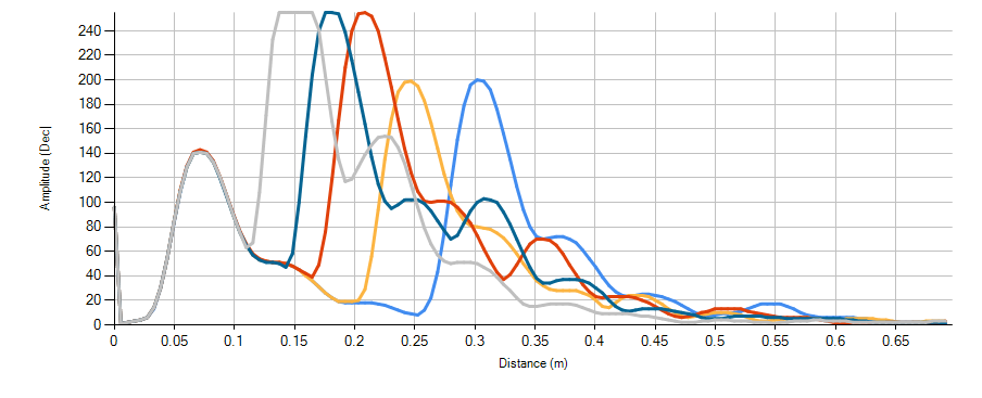
    In the first screen capture, you will see the false positive generated by the internal electrical coupling. This false positive is repeatable at approximately 5cm with an amplitude of 140. The actual object was positioned between 10~25cm (see the overlapping echo data dump results):

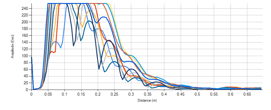
    In this second plot, the object was moved as close as possible to nearly 0cm. Here you will see that the actual acoustic echo returns far exceed the amplitude of the internally generated false positive:

    If you set the threshold to an initial level of 150, you can ignore the peak of the false positive, but still capture actual acoustic returns with override/mask the false positive.

    Here are the ultrasonic measurement results (UMR) when using the following register map config:

    UMR:


    Ultrasonic Measurement Results: (2017-11-09_110600)
    O1 Dist(m): 0.243
    O1 TOF: 05EE
    O1 Width(us): 792
    O1 Amp: 202
    Ultrasonic Measurement Results: (2017-11-09_110601)
    O1 Dist(m): 0.183
    O1 TOF: 0491
    O1 Width(us): 720
    O1 Amp: 170
    Ultrasonic Measurement Results: (2017-11-09_110603)
    O1 Dist(m): 0.147
    O1 TOF: 03C0
    O1 Width(us): 1020
    O1 Amp: 255
    Ultrasonic Measurement Results: (2017-11-09_110604)
    O1 Dist(m): 0.117
    O1 TOF: 0311
    O1 Width(us): 1020
    O1 Amp: 255
    Ultrasonic Measurement Results: (2017-11-09_110605)
    O1 Dist(m): 0.089
    O1 TOF: 026C
    O1 Width(us): 1020
    O1 Amp: 255
    Ultrasonic Measurement Results: (2017-11-09_110607)
    O1 Dist(m): 0.071
    O1 TOF: 0203
    O1 Width(us): 1020
    O1 Amp: 255
    Ultrasonic Measurement Results: (2017-11-09_110608)
    O1 Dist(m): 0.042
    O1 TOF: 0157
    O1 Width(us): 1020
    O1 Amp: 255
    Ultrasonic Measurement Results: (2017-11-09_110609)
    O1 Dist(m): 0.046
    O1 TOF: 0170
    O1 Width(us): 1020
    O1 Amp: 255
    Ultrasonic Measurement Results: (2017-11-09_110610)
    O1 Dist(m): 0.034
    O1 TOF: 0129
    O1 Width(us): 1020
    O1 Amp: 255
    Ultrasonic Measurement Results: (2017-11-09_110612)
    O1 Dist(m): 0.030
    O1 TOF: 0112
    O1 Width(us): 1020
    O1 Amp: 255
    Ultrasonic Measurement Results: (2017-11-09_110613)
    O1 Dist(m): 0.031
    O1 TOF: 0118
    O1 Width(us): 1020
    O1 Amp: 255
    Ultrasonic Measurement Results: (2017-11-09_110614)
    O1 Dist(m): 0.026
    O1 TOF: 00FD
    O1 Width(us): 1020
    O1 Amp: 255
    Ultrasonic Measurement Results: (2017-11-09_110618)
    O1 Dist(m): 0.023
    O1 TOF: 00ED
    O1 Width(us): 1020
    O1 Amp: 255
    Ultrasonic Measurement Results: (2017-11-09_110620)
    O1 Dist(m): 0.021
    O1 TOF: 00E1
    O1 Width(us): 1020
    O1 Amp: 255
    Ultrasonic Measurement Results: (2017-11-09_110622)
    O1 Dist(m): 0.018
    O1 TOF: 00CF
    O1 Width(us): 1020
    O1 Amp: 255

    Register Map:

    ;GRID_USER_MEMSPACE
    00 (USER_DATA1),00
    01 (USER_DATA2),00
    02 (USER_DATA3),00
    03 (USER_DATA4),00
    04 (USER_DATA5),00
    05 (USER_DATA6),00
    06 (USER_DATA7),00
    07 (USER_DATA8),00
    08 (USER_DATA9),00
    09 (USER_DATA10),00
    0A (USER_DATA11),00
    0B (USER_DATA12),00
    0C (USER_DATA13),00
    0D (USER_DATA14),00
    0E (USER_DATA15),00
    0F (USER_DATA16),00
    10 (USER_DATA17),00
    11 (USER_DATA18),00
    12 (USER_DATA19),00
    13 (USER_DATA20),00
    14 (TVGAIN0),AA
    15 (TVGAIN1),AA
    16 (TVGAIN2),AA
    17 (TVGAIN3),00
    18 (TVGAIN4),00
    19 (TVGAIN5),00
    1A (TVGAIN6),00
    1B (INIT_GAIN),40
    1C (FREQUENCY),32
    1D (DEADTIME),80
    1E (PULSE_P1),84
    1F (PULSE_P2),10
    20 (CURR_LIM_P1),40
    21 (CURR_LIM_P2),C0
    22 (REC_LENGTH),09
    23 (FREQ_DIAG),11
    24 (SAT_FDIAG_TH),22
    25 (FVOLT_DEC),69
    26 (DECPL_TEMP),CF
    27 (DSP_SCALE),00
    28 (TEMP_TRIM),00
    29 (P1_GAIN_CTRL),09
    2A (P2_GAIN_CTRL),09
    2B (EE_CRC),94
    40 (EE_CNTRL),00
    41 (BPF_A2_MSB),85
    42 (BPF_A2_LSB),8D
    43 (BPF_A3_MSB),F9
    44 (BPF_A3_LSB),A5
    45 (BPF_B1_MSB),03
    46 (BPF_B1_LSB),2D
    47 (LPF_A2_MSB),7C
    48 (LPF_A2_LSB),D3
    49 (LPF_B1_MSB),01
    4A (LPF_B1_LSB),97
    4B (TEST_MUX),00
    4C (DEV_STAT0),80
    4D (DEV_STAT1),00
    5F (P1_THR_0),02
    60 (P1_THR_1),44
    61 (P1_THR_2),44
    62 (P1_THR_3),44
    63 (P1_THR_4),55
    64 (P1_THR_5),55
    65 (P1_THR_6),9C
    66 (P1_THR_7),D0
    67 (P1_THR_8),52
    68 (P1_THR_9),0C
    69 (P1_THR_10),63
    6A (P1_THR_11),28
    6B (P1_THR_12),30
    6C (P1_THR_13),34
    6D (P1_THR_14),3C
    6E (P1_THR_15),00
    6F (P2_THR_0),02
    70 (P2_THR_1),44
    71 (P2_THR_2),44
    72 (P2_THR_3),44
    73 (P2_THR_4),55
    74 (P2_THR_5),55
    75 (P2_THR_6),9C
    76 (P2_THR_7),D0
    77 (P2_THR_8),52
    78 (P2_THR_9),0C
    79 (P2_THR_10),63
    7A (P2_THR_11),28
    7B (P2_THR_12),30
    7C (P2_THR_13),34
    7D (P2_THR_14),3C
    7E (P2_THR_15),00
    7F (THR_CRC),03
    EOF

  • Hi Akeem,

    thank you for your response.

    > The electrical coupling between OUTA/B and INP is unintended, but this is one of the negative trade-offs of the integrated driver and receiver IC.

    That's a big problem. In my understanding a proper decoupling of RX and TX signal path is essential for a bi-static mode. There's no benefit of a bi-static mode if parasitic signals are stronger than echo signals.

    Unfortunately your configuration example doesn't suit for our application. You have reduced RX sensitivity and TX signal force to minimum values. As described in my previous post this can't be an option for us. Your graphic shows echo signals within a ultra short range just up to 40 cm. This is not useable for us. In our case we need a range up to 3 m. This implicates a much stronger TX signal and much more sensitivity at larger distances. Thus, short distance echo signals and TX signal will always be merged.

    I don't see any option to go around the central problem, the coupling between TX an RX signal path.
  • Hi Marc,
    For my previous example, I forced a fixed-level time varying gain (TVG) of 32dB at the analog front end (AFE) of the PGA460, and small digital gain multiplier (DGM) of x2 at the digital signal processor's (DSP's) output. The example was intended to exclusively demonstrate the results for very short ranging. If you need up to 3m detection, you have two options:

    A) The PGA460 offers two driver presets (1 & 2). You can allocate preset 1 for the short range (sub-1m) with a low pulse count (sub-10), low driver current limit (sub-250mA), and low digital gain multiplier (sub x8). Preset 2 can then be allocated for +1m detection, with a large version of the aforementioned parameters. The system could then toggle between the short and long range preset to cover the entire range.

    B) Apply a ramping time varying gain (i.e. ramp from 32dB up to 62dB across the record length), and apply a large digital gain multiplier at a specified time in the record window (increase from x2 to x16 for improved SNR resolution/scaling). This would allow you to use a single preset to detect both short and long range objects.

    For a feasibility analysis, can you provide the following details:
    1) Transducer part number and specification (if not publicly available in a datasheet)
    2) Driver type and voltage
    3) Target type (size, shape, material)
    4) Environment (inside/outside)

    Even with weak drive conditions, 3m object detection is typically possible if the receiver's AFE and DGM are amplified.
  • Hi Akeem,

    thank you for your suggestions.
    We are going to test option A after making some mechanical improvements.
    Option B doesn't offer enough dynamic range.

    Some details:
    1) Transducer: Murata MA58MF14-7N
    2) Driver type and voltage: see BOOSTXL-PGA460
    3) Target type: different materials, but tested on wooden floor
    4) Environment: tested inside, intended to use outside

    Marc