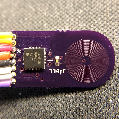
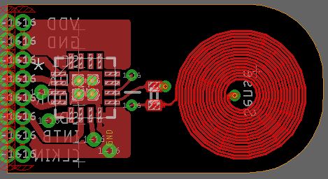
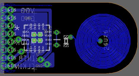
I have created a two-layer test PCB for this chip with a single coil (from WEBBENCH). It simply has the chip, the tank capacitor (330pF X7R), and the coil. See Attached photos. When I connect the sensor to a Teensy 3.2 and run the code written by Kylie Chesner, the chip and the MCU successfully communicate, but the outputs are always zero.

The code run was as follows:
#include <Wire.h>
int LDC = 0x2A;
int CH0MSB = 0x00;
int CH0LSB = 0x01;
long initial0 = 0;
unsigned long readChannel0(){
unsigned long val = 0;
word c = 0; //a word stores a 16-bit unsigned number
word d = 0;
c = readValue(LDC, CH0MSB);
d = readValue(LDC, CH0LSB);
val = c;
val <<= 16;
val += d;
return val;
}
void Calibrate(){
initial0 = readChannel0();
}
word readValue (int LDC, int reg){
int a = 0;
int b = 0;
word value = 0;
Wire.beginTransmission(LDC);
Wire.write(reg);
Wire.endTransmission();
Wire.requestFrom(LDC, 2);
while (Wire.available()){
a = Wire.read();
b = Wire.read();
}
value = a;
value <<= 8;
value += b;
return value;
}
void writeConfig(int LDC, int reg, int MSB, int LSB){
Wire.beginTransmission(LDC);
Wire.write(reg);
Wire.write(MSB);
Wire.write(LSB);
Wire.endTransmission();
}
void Configuration(){
writeConfig(LDC, 0x1A, 0x16, 0x01);//CONFIG
writeConfig(LDC, 0x14, 0x10, 0x02);//CLOCK_DIVIDERS_CH0
writeConfig(LDC, 0x1E, 0x90, 0x00);//DRIVE_CURRENT_CH0
writeConfig(LDC, 0x10, 0x00, 0x0A);//SETTLECOUNT_CH0
writeConfig(LDC, 0x08, 0x04, 0xD6);//RCOUNT_CH0
writeConfig(LDC, 0x19, 0x00, 0x00);//ERROR_CONFIG
writeConfig(LDC, 0x1B, 0x02, 0x0C);//MUX_CONFIG
}
void setup(){
Wire.begin();
Serial.begin(9600);
Configuration();
delay(500);
Calibrate();
pinMode(13, OUTPUT);
}
void loop(){
unsigned long data0 = readChannel0();
Serial.println(data0);
digitalWrite(13, HIGH); // Blink the onboard LED for signs of life
delay(200);
digitalWrite(13, LOW);
delay(200);
}
The output is as follows:

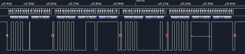
No matter where my metallic test object is in relation to the sensor, the oscilloscope always shows the output MSB and LSB to remain at zero. I have the SD, INTB, ADDR, and CLKIN pins tied to GND.
I have tried changing the clock dividers and the RCount but this didn't show any changes in the output.
What are some other possible steps that I could take to get this chip up and running?