This thread has been locked.

If you have a related question, please click the "Ask a related question" button in the top right corner. The newly created question will be automatically linked to this question.

IWR1443: Why the head part of each chirp data has a big bias?

Part Number: IWR1443

Hi, 

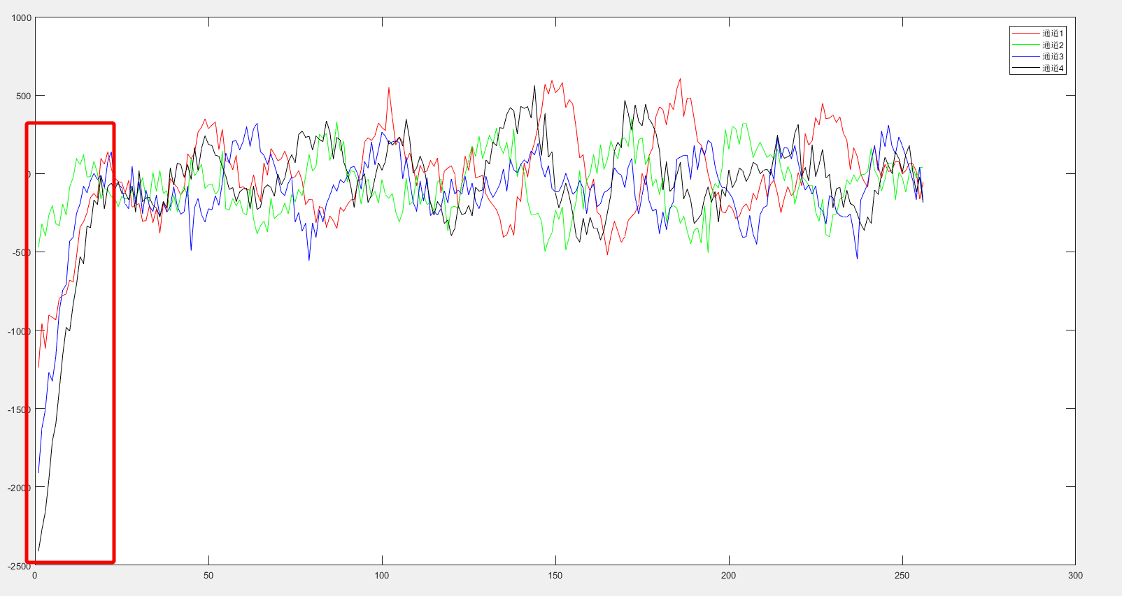
I set up a project to capture data by LVDS output, and found the head part of each chirp data has a big bias.

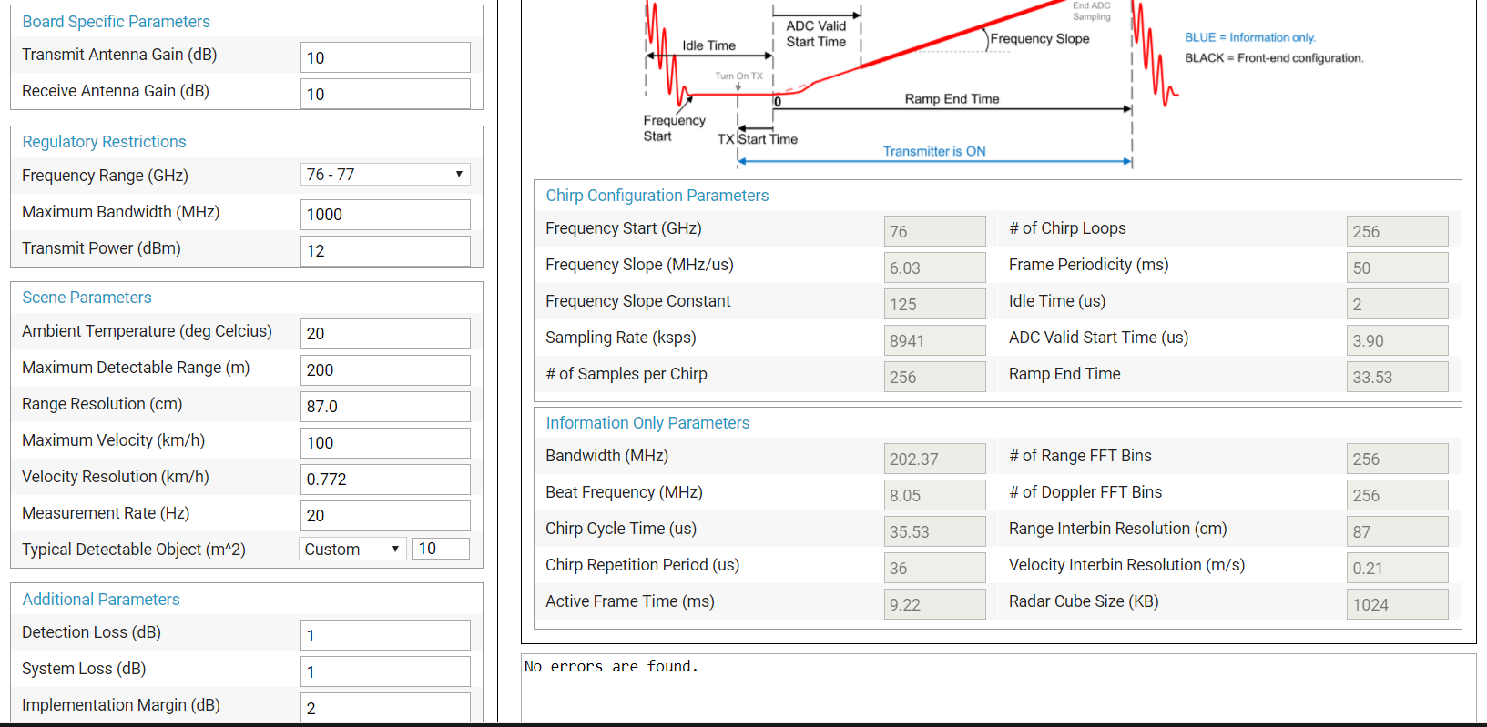
My configuration is profileCfg 0 77 5 5 29 0 0  9 1 256 12200 0 0 48.

What cause this? Idle time or adc start time?

Thanks!

  • Hello,

    For the start of each chirp, there is a ADC Start time, which allows for the Digital Front End (DFE) filtering to stabilize.   In mmWave SDK 1.1, there is also a DC Bias control, which has been added (there is a newer dfp and Radar Studio package also).   

    Initially you can design your radar parameters using the mmWave System Estimator - "dev.ti.com/.../"

    You can translate the parameters calculated into the StaticConfig, DataConfig, RampTimingCalculator, and SensorConfig

    In some cases The ADC Start time is increased, not just for the 99% settling, but further increased to remove the startup transient, in your case, this would be 

    the numb DFE outsamples / DFE out rate + existing ADC start time.

    There is an additional API for DC Bias removal.   I suggest you adjust the ADC Start time first.

    Regards,

    Joe Quintal

  • Hi, Joe,

             Thank you for your information.

              I tried to set the configuration in your recommended website, and finally find out a less ADC time and idle time. I am afraid it may be worse than my setting.