


Other Parts Discussed in Thread: SN74LVC2G17
We continue to use the IVC102 in a design (precision integrator measuring conductivity). Our circuit is fairly simple with the three internal capacitors selected in parallel. The schematic is below.
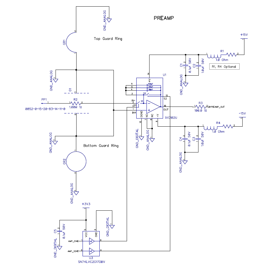
Featured is the use of an SN74LVC2G17 which cleans up the S1 and S2 signals (not that they will be messy.. but as a safety measure). Both DC rails are well regulated and include additional filtering.
The IVC102 data sheet specifies a reset sequence as follows:
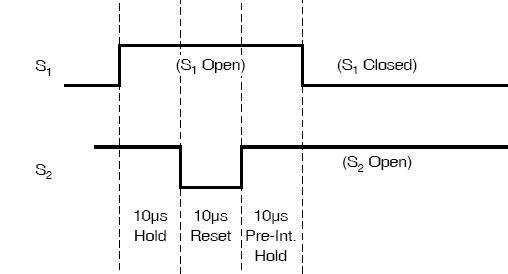
I interpret this to mean:
CLOSE S1 <-- set an initial state
CLOSE S2 <-- set an initial state
OPEN S2
OPEN S1
WAIT 10uS
CLOSE S2
WAIT 10uS
OPEN S2
WAIT 10uS
CLOSE S1
START INTEGRATION
Once S1 is finally closed, the integration starts and data may be taken.
We'd like to modify the sequence such that S1 is always closed. Therefore the alternate sequence would be:
CLOSE S1 <-- set an initial state
CLOSE S2 <-- set an initial state
OPEN S2
WAIT 10uS
CLOSE S2
WAIT 10uS
OPEN S2
START INTEGRATION
In my testing with the alternate reset sequence I am not getting any integration from the amplifier. There may be other reasons related to my code, but before I pull any more hair out, can TI tell me if the reset sequence published in the data sheet does more (internal to the IVC102) than simply close and open the switches?
