This thread has been locked.

If you have a related question, please click the "Ask a related question" button in the top right corner. The newly created question will be automatically linked to this question.

AWR1642BOOST: Is it possible to combine both Real and Complex ADC data formats within a single, advanced, sub-frame configuration?

Part Number: AWR1642BOOST

Hello;

Using the advanced frame configuration, is it possible to collect a sub-frame of chirps with Real only ADC data (to make use of the maximum 12.5Msps ADC), then another sub-frame with Complex ADC data? I'm having issues switching between Real collection and Complex collection as the dev board requires a power cycle before switching. I'm unsure why this is the case. 

Thanks,
Erik

  • Hello Erik,

    Seems like the ADCOUT CONF changes requries a power cycle.:

    Based on Radar Interface Document :

    " 5.2.2 Sub block 0x0082 – AWR_ADCOUT_CONF_SET_SB"
    This sub block contains static device configurations (applicable for the given power cycle) – regarding the data format of the ADC output (including the digital filtering).


    We will confirm this and recommend options accordingly.

    Thank you,
    Vaibhav
  • Hi Erik,

    The maximum range (or max IF frequency) that can be estimated using 'complex1X' @ 6.25 Mhz, and 'real' @12.5 Mhz is the same. This is because, for a given sampling rate fs, 'complex1X' provides 0 to fs, and 'real' provides 0 to fs/2 (ignoring the negative frequencies).

    So, in order to sample 0 to fs with the 'real' mode, you'll have to double the sampling rate to 2 * fs.

    Regards
    Anil
  • Hi Anil;

    The reason I'm interested in higher data rates is not for maximum range, rather for maximum velocity.

    Based on experimentation and documentation, the device does not seem capable of mixing Real and Complex data collection with any type of advanced frame configuration. I would like to confirm that statement with you.


    Thanks,
    Erik

  • Hi Erik, 

    That is correct. Real and complex data collection is not possible with any combination of 'Advanced Frame '.

    I still don't understand how maximum velocity improves with 'real' only mode. The maximum velocity is simply a function of chirp repeat rate, which is independent of the adc sampling frequency. 

    Regards

    Anil

  • Anil;

    According to the documentation, there is a minimum sample collection of 64 points. At 12.5 Msps, that caps your fastest chirp time at ~5us. If using complex mode, you can only make use of the 6.25 MSps collection rate, meaning your fastest chirp is ~10us. Once you add in settling time required for clean data collection, this factor of 2 difference in chirp time drastically helps the maximum unambiguous velocity calculation. 

    Now, according to another TI employee, it is possible to collect 16 samples, but I still haven't gotten a response as to how to actually achieve that as the existing API for sensor control throws a configuration error if anything less than 64 samples is requested:

    https://e2e.ti.com/support/sensor/mmwave_sensors/f/1023/p/649002/2388052#2388052

    Until then, I need to work with the 64 sample minimum requirement. 

    If there is something I'm misunderstanding, please let me know. Thank you for your response.
    -Erik

  • Hi Erik,

    The documentation regarding profile config is still to be updated. The minimum number of ADC samples per chirp is 4 in 0.9 (was 64 in 0.7).

    What is the error that you are seeing?

    Regards
    Anil
  • Hello;

    I am getting this configuration error:

    #define RL_RET_CODE_PF_IDLE_TIME_1INVAL_IN            (38U) /* Maximum DFE spill time >
                                                                    PF idle time const */

    After the mmw_demo project prints this error message: [Cortex_R4_0] Error: MMWDemoMSS mmWave Config failed [mmWave Error: -3108 Subsys: 38]

    Thanks,
    Erik

  • Hi Erik,

    The error doesn't have anything to do with the number of samples. Could you try out the chirp config that you've created in the 'Ramp timing calculator' from radarstudio, and see if it is valid?

    Regards
    Anil
  • Anil;

    The Ramp timing calculator won't allow me to enter a number less than 64 samples.

    Regards,
    Erik
  • Hi Erik,

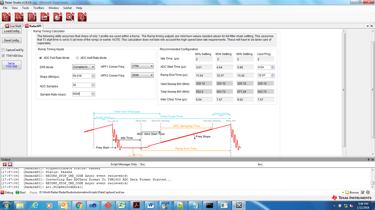
    Sorry about that. We will be (fixing) and releasing a newer version of RadarStudio soon. For the time being, I can share the following image for 32 adc samples.

    If you can share your desired slope and sampling rate, I can run the same through the updated 'ramp timing calculator' and send it to you.

    Regards

    Anil