This thread has been locked.

If you have a related question, please click the "Ask a related question" button in the top right corner. The newly created question will be automatically linked to this question.

IWR1642BOOST: What ECOs are required to route SPI through J5 and J6?

Part Number: IWR1642BOOST
Other Parts Discussed in Thread: IWR1642

Hello, 

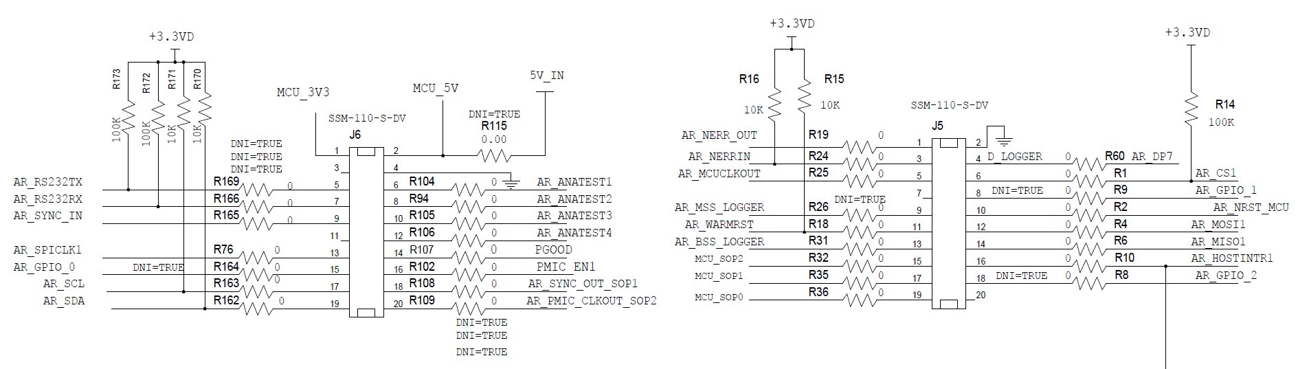
I have been trying to get the SPI signals in both master and slave configurations out of the pins on J5 and J6 (AR_SPICLK1, AR_CS1, AR_MOSI1, AR_MISO1). So far, I have not been able to get any signal out of the pins when writing to the bus in either slave or master configuration. I have verified the lack of signal on a scope from the IWR1642 EVM. Whereas, independently hooking up an Arduino micro resulted in an observable signal on the scope. 

I have followed all software examples to the letter, so it may be a hardware issue. So are there any ECOs that need to be carried out to get these pins working?

Thank you

  • Hi Herman,

    I've asked an IWR Expert to look into this for you. He should have a response for you in the next couple of days.

    Meanwhile I'd recommend you look at this TI Design which uses SPI: www.ti.com/.../TIDEP-0091


    Cheers,
    Akash
  • Hi Herman,

    The first suggestion I have is to check that you are probing the correct pins.  I imagine that you are, but just to be sure I am attaching a snapshot of the J5 J6 schematic.

    The second suggestion is to check the pinmux.  As Akash mentioned, check the level sensing demo for a simple example on how to initialize SPI and send a simple transfer.  It also includes the correct pinmux initialization.  There should be nothing else needed.  Check that you are performing all the SPI setup calls that the demo does, and check that there isn't any pinmux initialization on the same pins after the SPI pinmux. Finally, SPI initialization should be done from the Init task, not from main.

  • Doing the pinmux initialization from the init task did the job. Thank you.