This thread has been locked.

If you have a related question, please click the "Ask a related question" button in the top right corner. The newly created question will be automatically linked to this question.

CCS/IWR1443BOOST: IWR1443BOOST

Part Number: IWR1443BOOST
Other Parts Discussed in Thread: IWR1443

Tool/software: Code Composer Studio

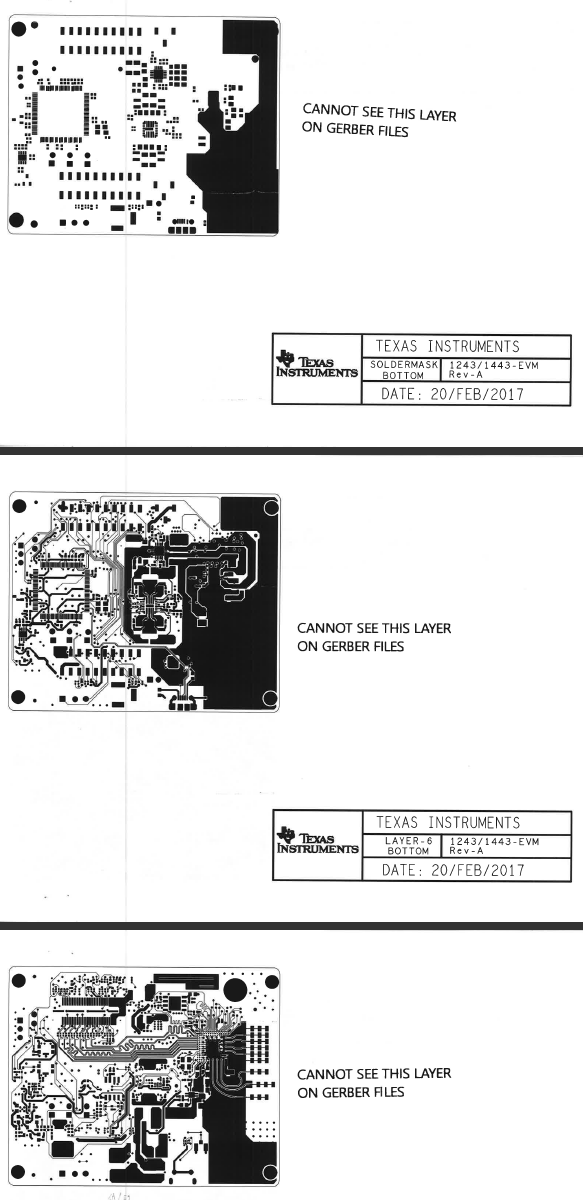
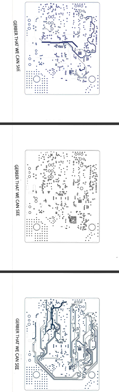
We cannot find the tricky antenna layer in the Gerbers in the ZIP files  .

We can see them on the PDF but not the Gerbers.  They seem to be missing.  Please send a link to the Gerbers for all of the layers on the IWR1443BOOST board.

Also, where can the Schematic be found in a format that can be edited so that we do not need to redraw everything?

Thanks, Peter

===============================================

top is Gerber.  Bottom is PDF with similar layer but no antennas layers on the right.

  • Hello,

    The schematic and layout are done in the Cadence Allegro tool.

    I have opened the 1443 BOOST board file, in the PCB editor and re-exported the artwork and drill files,  they are in the attached ZIP.

    There is a hardware design guide attached, it discusses the RF connections (special layer 2 hole), layer 1 Grounded Coplanar Waveguide, RF stripline and the antenna.  In your top colored picture, the etch was turned off.   The RF traces and antenna are not schematic elements, they are drawing in layout.

    The hardware design guide has the references for the GPCW, the antenna dimensions, depend on your needed antenna design.

    We are working on conversion to Altium, We may have an xWR1642 in Altium that is different by the LVDS lanes, you can difference the 1443, and 1642.  I will

    forward the Altium project as it is not online yet.

    Let us know if the newly generated gerber solves part of your request.

    Regards,

    Joe Quintal1219_1443gerberdrill.zipHardwareDesignChecklist_V0p7fix_IWR1443_SWRR150.xlsxmmWave_hw_design_guide_rev_9.pdf

  • We can see 4 layers but 3 layers are missing.  Our Sunstone software can do 6 layers.   Is the IWR1443BOOST a 7 layer board. ?  Are some layers turned off or do you think it is our software?

    Thanks, Peter

  • 1443_layout_122617_check.zipI have taken the 6 layers, Top, L2, L3, L4, L5, and Bottom and plotted them in Cadence PCB Designer, and imported the .art files to GC Prevue

    artwork viewer they are all present.

    I have included the .art, .gwk (gerber import to GC Prevue), and .pdf files plotted from Cadence.

    in the IWR1443BOOST_RevA layout, you have to line up the proper files.

    pg#, page name, filename (.art)

    1,  Silkscreen Top, SST

    2,  Soldermask Top, SMT

    3,  Layer - 1 Top, TOP

    4, Layer 2, L2

    5, Layer 3, L3

    6, Layer 4, L4

    7,  Layer-5, L5

    8,  Layer-6 Bottom, BOTTOM

    9,  Soldermask Bottom, SMB

    10,  SilkscreenBottom, SSB

    11, Outline, OUTLINE

    Please check over the files in this zip, and tell me if you are still missing something.

    Regards,

    Joe Quintal

  • We sent our board shop the Gerbers to see if we can manufacture a product using the IWR1443 before we get into the heavy design and development of a special board.  We received this from our board shop, Sunstone, which is a large shop.  Is there any way to loosen the specs up?

    Thanks, Peter

    -----------------------------------------------
    "Sorry, this PCB turns out to be a NO BID.  
    The spacing is too tight for via fill, need 5mils minimum.
    Vias too small for fill, minimum fillable size is .010.
    Per notes, mask openings for BGA shall not be changed. Current openings are .78mils, which is too small. Minimum mask annular ring allowed is 3mils.
    Overall it’s too tight for us.
    As an FYI, Rogers isn’t available in mixed copper weight as standard. That’s generally a special order item."

  • Hello Peter,
    Yes the layout specifications are challenging for the board. The current EVM board vendor is Streamline Circuits.

    I am sorry I don't have a different layout specification for you. The Rogers 4835 LoPro 1/2 oz ED copper is what is used for the RF
    top layer, 4 mil core.
    Regards,
    Joe Quintal