This thread has been locked.

If you have a related question, please click the "Ask a related question" button in the top right corner. The newly created question will be automatically linked to this question.

DDC264: INL spec

Part Number: DDC264

Hello,

DDC264 datasheet defines "INL = ±0.025% of Reading ±1 ppm of FSR" on its1st page, 1ppm of FSR is close to 1LSB, so does it mean it is "±0.025%" error with 1LSB value read out of ADC?  I am confused how to make such low and precision input signal to generate 1LSB code.  And may I know why define this data?

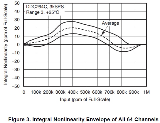
And there is a figure chat to define full linearity as following, find that INL is worst for the middle level input signal. why is it so big differnce from the both end

  • Jerry,

    Sorry for the delay during the holidays. Did you end up figuring out what you needed?
  • Hi Amy,

    If possible, please share us your minds about our questions, thank you.

    Regards,
    Jerry
  • Hi Jerry,

    Not sure I follow all your questions, but basically the linearity error at any given point is given as a fix factor no matter what the input is (the 1ppm...) + a factor that is proportional to the value of the input (the 0.025%...). I.e., when the input is really small, only the first (fix) factor counts but as the signal becomes bigger, the proportional factor takes over.

    On the figure, and why the error is bigger on the middle, it is because here the error has been plotted as the deviation to a line going through the zero and full-scale values. As such, right at those two points the error is zero and bigger in the middle. Basically the non-linearity has to be measured respect to a "line" and the choice on those plots was that (an end-point line).  

    Regards,

    Eduardo 

  • Hi Eduardo,

    Thanks. But may I know what's the absolute input voltage when TI make the definition "INL = ±0.025% of Reading ±1 ppm of FSR"?

    Regards,
    JerryL
  • Hi Jerry,

    Not sure I follow you... The input to the device is current (or charge, once you set the integration time...), not voltage. The INL number is given as a function of that current/charge. It is not one number. I.e., the INL will barely be 1ppm of the full scale range (FSR) when the input is very small (close to zero), but with a full-scale input the INL could be as large as ±0.025% of that input.

    If you are asking what is the max current for that spec (what is that full-scale range), that is given on top of the table: Range 3=150pC (maximum charge). There are two integration times 166us or 333us depending on the version of the 264 you are talking about (CK or C). Hence max current: 150pC/166us or 150pC/333us.

    As you are asking "voltage", I wonder If you are looking for 2nd order effects, like the input bias voltage. Ideally the voltage of the input is zero, but it actually has some small value depending on the input current. Please see figures 15 and 16 to get a sense for it.

    Best regards,

    Eduardo

  • Hi Eduardo,

    Yes, the input should be current. I am confused by the definition "INL = ±0.025% of Reading ±1 ppm of FSR". So can I understand it as the worst INL of DDC264 is ±0.025% when the 1st stage integrator output is close to FSR? ±0.025% is relative to FSR. "Reading ±1 ppm" means alsmot 1LSB step change.

    For Figure 3, the curve of INL vs input signal. The INL of high end point is taken as zero due to only concern linearity but not a specific point. Thus ±0.025% is removed, the worst INL should be in the middle level input due to accumulation.

    Thanks for your reply.

    Regards,
    JerryL
  • Hi Jerry,

    Maybe let me start from the beginning although I may explain some stuff that you already know...

    When you use the DDC to measure a given current, you expect it to give you something very close to the real value but with some error. For instance, if you don't apply any input, you would expect the device to output "zero" (well, actually 4095 in the DDC264) but you may get 4200. The difference between the two is called zero error (as it is the error for zero input). If you inject the FSR (say 100pC if you are in Range 2) you should be getting 2^20-1 code but may get something else. That would be your full-scale error.

    If you inject any other value in between you may expect something but will get something else. Etc... In order to give an indication of what that error can be the DS lists several parameters. One way is to sweep the input from zero to FSR and take measurements. Then fit a line to the results and give a description of the line and the error to that line. Of course, there are many criteria to choose that line but regardless, once we choose that line, we put some data to explain how "wrong' that line is respect to the ideal one. For instance, we can give the error on the slope (gain error) and on the crossing with zero (offset error). Then we give the INL (the error, the difference between the real and the line). 

    Imagine that no matter what point we measure (what input we put, small or big), the difference between what we measure and the line is within 0.1pC. Then you could say that INL=+/-0.1pC, regardless of the measured magnitude. This is actually the case for many ADCs. In the DDC we choose what is called a best fit line (for the value on the tables, not the graph). It would be too long to explain what best line we pick, but it results on the error actually not being constant, but growing with the measurement. Smaller signals have smaller deviation to the line and bigger signals, have bigger. Hence the INL is given as a factor proportional to the measurement (the reading): 0.025% of reading. But somebody would then think that the error is zero when the signal is zero, which is not the case. Hence the 1ppm.

    In the graphs, as mentioned, the line is an endpoint line, so, the error between what you read and the line on the extremes is zero and the difference is biggest somewhere in between. For instance, in figure 1, Range 2 (100pC), if you input 40pC you would get about 400k reading. The graph is showing that actually you may have an error of 20LSBs when you are measuring that value. The error is the difference between what you measure and the end-point line. Nevertheless, remember that the line does not represent zero absolute error. For instance, there may be a 5% gain error... so you would still have to add that to the 20LSBs.

    Hope this helps. If not, I recommend you look at http://www.ti.com/lit/an/slaa013/slaa013.pdf or any other book where these concepts would be explained more in detail.

    Best regards,

    Eduardo

  • Hi Eduardo,

    Thank you for the sharing. So for INL = ±0.025%, it is not only for Reading ±1 ppm of FSR, but for Reading ±"any" ppm of FSR.

    I wonder if Figure 1 is generated from 1 specific device only. Because for a general ADC, the INL error value is changed from device to device for a constant input.

    Regards,
    JerryL
  • Hi Jerry,

    I think there is some confusion on the way to read the INL spec. First term is ±0.025% of Reading. I.e., if the input is for instance 20pC, this error term on whatever the ADC returns is ±0.025% * 20pC. The 2nd term is constant, no matter what the input is. In this case ±1 ppm of FSR. If one is using Range 3, then it is ±1 ppm of 150pC. So, the total typical INL error for 20pC input would be  ±0.025% * 20pC ±1 ppm of 150pC. To this, you would have to add the offset and gain errors...

    On figure 1, yes, this is likely generated from one typical device. I.e., other devices will be close to this, but not exactly the same. 

    Not sure what you mean for your last sentence... In a general ADC, a typical spec (whatever that is, INL, offset, gain...) is obtained usually as an average of many devices... Certainly in the DDC, the INL for a given device will be different than that from another device  (like for any other spec), but it'll be close to the typical INL, which is what is listed on the DS. It is true that in a generic ADC, usually the INL is a constant value independent of the input to be measured.

    Regards,

    Edu

  • Hi Edu,

    Yes, I misunderstand "INL = ±0.025% of Reading ±1 ppm of FSR". It should be "INL = ±0.025%(typ.) of Reading plus ±1 ppm of FSR" for any input signal between 0~FSR(i.e. 12.5pC, 50pC, 100pC, 150pC), does it make sense?

    1ppm of FSR is about equal to 1LSB since ADC resolution is 20Bit, why not put it into offset error? For the offset error in the spec, 500ppm(typ) of FSR defined, also relative to FSR.

    Regards,
    JerryL
  • Hi,

    Not sure why you add "typ". The whole equation is for the typical INL (kind of average value across any channel on any part). But what is not right is the "for any FSR". The INL spec is given under the conditions on top of the table, which I believe list only one Range (FSR). There should be plots showing the INL for different ranges and you probably will see that it gets worse as you select a more sensitive range.

    And you are right, 1ppm~1LSB. The reason is that for signals that are very small, the "0.025% of reading" will be very small (<<1ppm). If you removed the 1ppm and left only the 0.025%... you would be basically saying that all the measurements for very small signals fall right on top of the line, but it is not true. They can actually be 1ppm away.

    Best regards,
    Edu