


Tool/software: Code Composer Studio
Hi there,
first of all my source code:
#include <msp430.h>
#include <stdint.h>
#include <stdio.h>
/**
 * main.c
 */


uint32_t TIME[5];
void SPI_init(void);
int t,inter_stat;
void SPI_write_config1(uint8_t,uint8_t);
void SPI_write_config2(uint8_t,uint8_t);
void SPI_write_interrupt_mask(uint8_t,uint8_t);
uint8_t SPI_read_interrupt_status(uint8_t);         // ist unnötig kann auch im singlebyte gelesen werden und in der main so konfiguriert
uint8_t SPI_read_singlebyte(uint8_t);
uint32_t SPI_read_longbyte(uint8_t);

int main(void)

{
      uint32_t Time1_6;
      uint8_t i;

      WDTCTL = WDTPW | WDTHOLD;       // stop watchdog timer

      SPI_init();
      SPI_write_config1(0x40,0x03);         //write register adress 00h with commands
      SPI_write_config2(0x41,0x40);
      //inter_stat = SPI_read_interrupt_status(0x02);
      //SPI_write_interrupt_mask(0x43,0x00);
      Time1_6 = SPI_read_longbyte(0x90); // lesen der TIME 1_6 Register mit auto inc


      return 0;

}

uint32_t SPI_read_longbyte(uint8_t adress)
{
    uint32_t y = 0;
    uint32_t x = 0;

    P2OUT &= (~BIT2);                // Select Device

    while(!(UCB0IFG & UCTXIFG));     // wait for TXBUF
    UCB0TXBUF = adress;              // send adress für ...

    while(!(UCB0IFG & UCTXIFG));     // wait for TXBUF
    UCB0TXBUF = 0;                   // Dummy write to read data

    while(!(UCB0IFG&UCRXIFG));       // Wait for RXBUF ready
    y = UCB0RXBUF;

    x |= (y << 16);

    while(!(UCB0IFG & UCTXIFG));     // wait for TXBUF
    UCB0TXBUF = 0;                   // Dummy write to read data

    while(!(UCB0IFG&UCRXIFG));       // Wait for RXBUF ready
    y = UCB0RXBUF;

    x |= (y << 8);

    while(!(UCB0IFG & UCTXIFG));     // wait for TXBUF
    UCB0TXBUF = 0;                   // Dummy write to read data

    while(!(UCB0IFG&UCRXIFG));       // Wait for RXBUF ready
    y = UCB0RXBUF;

    x |= y;

    while (UCB0STAT & UCBUSY);       // Wait for TX complete

    P2OUT |= (BIT2);                 // Unselect Device

    return x;
}


void SPI_write_config1(uint8_t adress,uint8_t value)
{

    P2OUT &= (~BIT2);                // Select Device

    while(!(UCB0IFG & UCTXIFG));     // wait for TXBUF
    UCB0TXBUF = adress;              // send adress to register 00h

    while(!(UCB0IFG & UCTXIFG));     // wait for TXBUF
    UCB0TXBUF = value;               // write a command to register 00h

    while (UCB0STAT & UCBUSY);       // Wait for TX complete


    P2OUT |= (BIT2);                 // Unselect Device
}

void SPI_write_config2(uint8_t adress,uint8_t value)
{

    P2OUT &= (~BIT2);                // Select Device

    while(!(UCB0IFG & UCTXIFG));     // wait for TXBUF
    UCB0TXBUF = adress;              // send adress to register 01h

    while(!(UCB0IFG & UCTXIFG));     // wait for TXBUF
    UCB0TXBUF = value;               // write a command to register 01h

    while (UCB0STAT & UCBUSY);       // Wait for TX complete


    P2OUT |= (BIT2);                 // Unselect Device
}

uint8_t SPI_read_interrupt_status(uint8_t adress)
{
    uint8_t rcv;
    //uint8_t clear = 0x1F;          // Clear interrupt flags??
    P2OUT &= (~BIT2);                // Select Device

    while(!(UCB0IFG & UCTXIFG));     // wait for TXBUF
    UCB0TXBUF = adress;              // send adress to register 02h

    while(!(UCB0IFG & UCTXIFG));     // wait for TXBUF
    UCB0TXBUF = 0;                   // Dummy write to read data

    while(!(UCB0IFG&UCRXIFG));       // Wait for RXBUF ready
    rcv = UCB0RXBUF;

    while (UCB0STAT & UCBUSY);       // Wait for TX complete

    P2OUT |= (BIT2);                 // Unselect Device

    return rcv;
}

void SPI_write_interrupt_mask(uint8_t adress,uint8_t value)
{

    P2OUT &= (~BIT2);                // Select Device

    while(!(UCB0IFG & UCTXIFG));     // wait for TXBUF
    UCB0TXBUF = adress;              // send adress to register 01h

    while(!(UCB0IFG & UCTXIFG));     // wait for TXBUF
    UCB0TXBUF = value;               // write a command to register 01h

    while (UCB0STAT & UCBUSY);       // Wait for TX complete

    P2OUT |= (BIT2);                 // Unselect Device

}


void SPI_init(void)
{

// Enable PIN aktivieren für Register Zugriff//
P6DIR |=BIT5;                          // OUTput enable Pin for TDC7200
P6OUT |=BIT5;                          // Output HIGH enable Pin aktiv

// SPI Pins Auswählen//
P3SEL = BIT0 + BIT1 + BIT2;
P2DIR |= BIT2;                        // PIN2.2 set as Chipselect
P2OUT |= BIT2;                        // PIN2.2 set the chipselect Pin high

// Konfiguration des SPI-Registers//
UCB0CTL1 |= UCSWRST;
UCB0CTL1 |= UCSSEL_2;

UCB0CTL0 = UCMST+UCMSB+UCCKPH+UCSYNC; // SPI Konfiguration (MasterMode;SynchroneMode;Clock_polarity;MSBfirstMode)

UCB0BR0 = 0x02;                       // Prescaler
UCB0BR1 = 0;


UCA0MCTL = 0;                         // No Modulation
UCB0CTL1 &= ~UCSWRST;                 // disable software reset
//UCB0IE |= UCRXIE;                   // Enable USCI_B0 RX interrupt
}
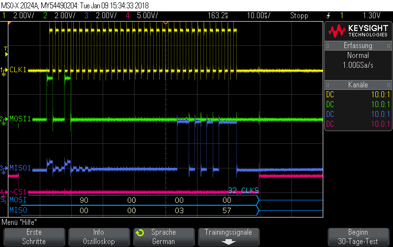
i try to read the TIME 1 register with the modified example function from TDC7200_basic_spi_rw: uint32_t TI_TDC720x_SPILongReadReg(uint8_t addr).
the result of this is that the clock stay low after each bit shift command:
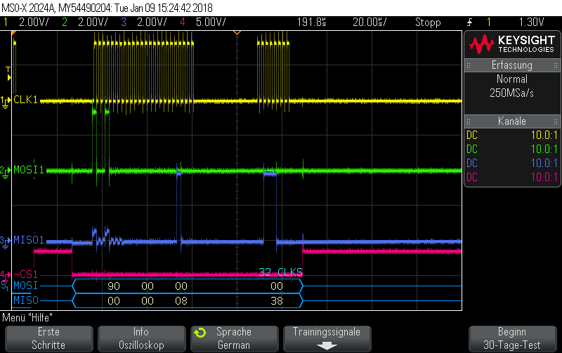
after that i try to comment out the bit shift operations after each y buffer receive and all while(!(UCB0IFG & UCTXIFG)); loops. Now i get a what i want a 32 clk cycle whithout any breaks:
My Question is: Is it possible to read my TIME register and the other only read registers with this function and if its possible how i solve it?
and how can I use this function with the autoincrement bit?
thanks in advance
greets Ben

