Hi,
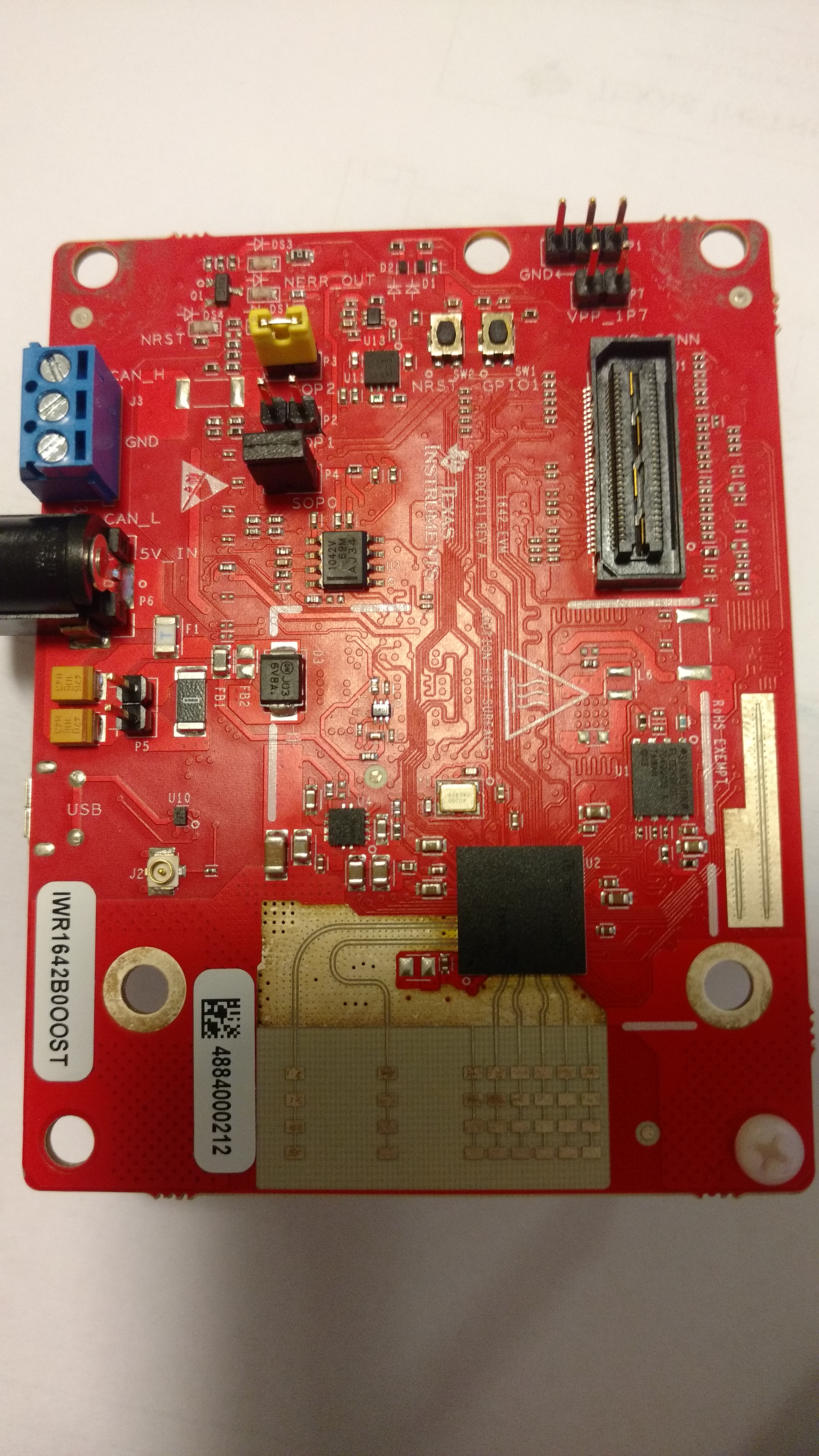
my IWR1642BOOST is not booting properly. After powering the board the 5V red led and the yellow NRST led are blinking.
I'm unable to connect to the serial port for flashing.
Can you help me to understand what's going on?
Regards,
Luca
Hi,
my IWR1642BOOST is not booting properly. After powering the board the 5V red led and the yellow NRST led are blinking.
I'm unable to connect to the serial port for flashing.
Can you help me to understand what's going on?
Regards,
Luca