This thread has been locked.

If you have a related question, please click the "Ask a related question" button in the top right corner. The newly created question will be automatically linked to this question.

DRV5032: DRV5032 vs. MMS1X1 Output Waveform Difference

Part Number: DRV5032
Other Parts Discussed in Thread: DRV5055-Q1, DRV5012

Dear TI Support Team

       We want to promote DRV5032 to replace MMS1X1H(Hall Sensor) on Gas Meter.Customer select DRV5032FD with unipolar output to test,They connect OUT1 pin and OUT2 to one output signal and test the waveform contrasted MMS1X1H's waveform,they found the duty cycle of DRV5032FD is about 50% that is similar to MMS1X1H,but the period of DRV5032FD is about 6 seconds that is twice MMS1X1H(3 seconds).

How can we do some change to reduce the output period from 6s to 3s? so customer don't need to change the metering software.

DRV5032FD Output waveform:

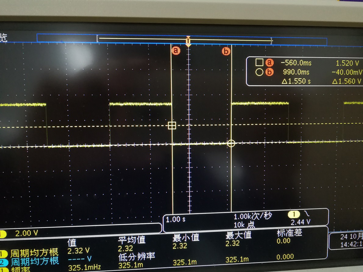
 MMS1X1H Output waveform:

  • Hello Yulei,

    Your description of the test procedure is not clear to me.How exactly did you excite the sensors? Did you use a time-varying current or a moving permanent magnet to generate the input flux signal? Did you apply the same excitation to both sensors? FYI you can use a linear Hall sensor such as the DRV5055-Q1 to measure the flux signal you are applying to the sensor. Also note that the two sensors have different BOP/BRP thresholds which means they will not switch at the same input value.

    Best Regards,

    Harsha

  • Yulei,

    Couple of things:

    1) The DRV5032FD has push-pull outputs and NOT open-drain. Therefore, connecting OUT1 and OUT2 together will cause them to fight and load each other down, creating unpredictable transient responses. Does the response improve if you test each one individually without connecting them together?

    2) Since the MMS1X1H is a Hall Latch sensor (see transfer function) I would recommend the DRV5012 (instead of the DRV5032FD)

    Best Regards,
    Harsha